Hello wise guys 😀
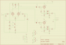
I build a LTP using a simple CCS at the tail to create a phaseinvertes and highly symetrical signal. Driving performance is not need but it should symetrical as possible. It works fine! I add for every phase a simple cathode follower to get an low impedance output ( ~600 Ohm ).
Unfortunately if I connect the cathode follower to the LTP the amplitude of both stages ar heavy different ( one is ~ -6dB ).
I do not understand this issue because the Zin of the cathode follower are ~ 8Meg which should not load the LTP.
Any tipp for me??? Sorry I´m a beginner in tubes ( but not in electronic 😉 )so if this a stupid question be patient. If we ever meet us I spend a good German beer!
Bestr regards
Karsten
Attachments
OK, let me earn this beer.
First, a general observation- if you're going to use an ECC83-type of tube, you need MUCH higher plate load resistors. The huge second harmonic will largely cancel because of the push-pull operation, but third and fifth will be pretty high. You want at least 100k, and much more if you can manage a nice, large B+ rail. 300k isn't too high.
Second, you can make things simpler and solve your problems simultaneously. Get rid of the resistor in the cathode (R4). Ground the far end of the grid leak resistor (R1) instead of returning it to the cathode. Ground the other grid (getting rid of the 1M grid leak for that half). Your grid stoppers can be greatly reduced- 1k is more than enough.
Hey Sy,
O.K. beer is reserved for you 🙂 Best of german beer is "Flensburger" for my opinion ( Town in the verry north of Germany ).
I tried your advice to ground R1 grid leak resistor. Also I ground R8 instead to connect it to R4 ( cathodes of LTP ) and leaving both grid stopper ( yepp, will reduce them to 1K ). Well, don´t work. The signal amplitude at both plates are quite different now. Also I do not have any bias ( no current through R4 ).
On all examples of LTP I have seen the Grid-leak resistors was connected "behind" the bias resistor and the long tail resistor to ground. This is replaced by the CCS and works fine for me but have the issue with the cathode follower ( Is there a common abbrevation for "cathode follower in english ? )
Concerning your first hint about harmonic distortion. I choosed the ECC83 ( 12ax7 ) because I would like to get a most linear out ( it´s simply the out stage of all the tubes before 🙄 ). The best case will be to have no or less amplification. I choosed the bias to 1V to get middle workping point on a loadline Va=200V / Ra=68K. HT is ~ 250V and for the long-tail I assumed ~ 50 V.
The question is why the cathode follower bred the LTP out balace concerning the signal amplitude?
Thanks a lot for your help!
Regards
Karsten
P.S. sorry for my bad english...😱
My apologies; I hadn't noticed that you'd returned the CCS to ground instead of to a minus rail. That means your biasing won't work- you're not actually running constant current. If you want to DC couple the input at DC ground, and likewise have the other grid at DC ground, the CCS won't have enough headroom to operate. The CFs are innocent bystanders.
Two choices. Best would be to use a low voltage DC rail (-9V is more than enough), then return the input grid leak to ground as I suggested and return the other grid to ground (no 1M resistor and no biasing resistor!).
The other choice is to capacitor couple the input so that the tube can "float" on a few extra volts, then using a bias resistor, return both grids to the "floating" potential.
Yeahh, and me too. I used all time a capacitor to couple the input. Sorry, don´t updated the schematic.
So we are back to my origin issue.🙁 The LTP and CCS works fine without to connect the CF to the anodes of the LTP. Without the second tube ( ECC81 ) the Anodes of the LTP are connected via C2, R10, R11 and R13 to ground. For that there is a load (AC concerned) of 1.022Meg. With this load the LTP works fine.
The CF should have a Zin of ~7.5Meg. For that I do absolutly not understand Why the amplitude of both phases are different. I wonder that one stage have 1/2 less amplidue... It´s magic for me...
Any ideas?
Regards
Karsten
Well, it doesn't really matter what the CF impedances are as long as they're the same. If you see an imbalance, that means you've made a wiring mistake or accidentally used the wrong value resistor somewhere.
So,I´m not to stupid to think that this schematic should work?
Wiring is O.K. because I use a program ( Eagle) and a PCB. It´s much load to route and make a PCB for a Test-board. But it´s quite more secure.. Also I double checked the resistor values.. Everyting O.K.
It´s possible to have a Tube which is quite unbalanced at the systems? 20% is a "normal" difference but 50%. Furthermore the bias on both systems via R12 and R17 ( 2,0V at 560Ohm are the same )...
Really strange....
Karsten
Take a look at my recent post on LTP balance. If the CCS is working, the tubes can be fabulously mismatched with no effect on balance.
Yepp, I folowed the thread. That´s why I use the CCS at the LTP.
Well, it´s the CF or better the coupling between the LTP and the both CF which do not in balance. Just run the CF without coupling to the LPT and feed them with the same singal amplitude I get the same amplitude at the output. So I can assume that the systems of the CF within the Tube are quite similar.
There must be a strange thing while coupling the LTP to the both CF...
O.K. I try to change the couple "C"´s ...
O.K. lost for today. It´s late in the night, better to stop here.
Thanks a lot for your help!
Regards
Karsten
Thanks a lot for your help!
Regards
Karsten
Just run the CF without coupling to the LPT and feed them with the same singal amplitude I get the same amplitude at the output. So I can assume that the systems of the CF within the Tube are quite similar.
That may not be so. If the source you drive them with has low Z, you may not see a difference.
Try this- reverse the CFs and see if the imbalance moves with them.
Hey, Back on work again...😀
So I checked teh LTP/CCS on symetrical amplitude without coupling capacitors to CF stage and without to put the second tube into the PCB. Work fine.
If I insert the second tube to the PCB the CCS goes out of work. It provide the cathode current but not as a constant source. The virtual GND on buttom of R4 ( bias resistor ) moves down from 6.5 V to 3V.
Well, in fact I do not know why the CCS change it´s working point if I plug in the second tube.
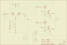
So now I try to use an other tube as LTP ( ECC82 ) which need more current in a center based working point. For that I calculate Ra=22K, Rb=1K, CCS current = 6mA
Hopfully this will enhance the stability of the CCS...
Regards
Karsten
So I checked teh LTP/CCS on symetrical amplitude without coupling capacitors to CF stage and without to put the second tube into the PCB. Work fine.
If I insert the second tube to the PCB the CCS goes out of work. It provide the cathode current but not as a constant source. The virtual GND on buttom of R4 ( bias resistor ) moves down from 6.5 V to 3V.
Well, in fact I do not know why the CCS change it´s working point if I plug in the second tube.
So now I try to use an other tube as LTP ( ECC82 ) which need more current in a center based working point. For that I calculate Ra=22K, Rb=1K, CCS current = 6mA
Hopfully this will enhance the stability of the CCS...
Regards
Karsten
Attachments
Masurements
Yepp,
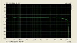
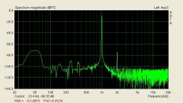
Well it´s running so far. But there is an bad feeling about the instable CCS... This MUST be solved for my opinion befor I go forward... Any hints are verry welcome!
Actual masurements see attachments. Th aplitude difference at 1Khz 0dB is no 9mV which is not so bad I think. Out of Phase signal is 40mV using the ADD functionality of my scope ( which I do not fully trust ).
Thanks a lot for your Help!!!
Regards
Karsten
Yepp,
Well it´s running so far. But there is an bad feeling about the instable CCS... This MUST be solved for my opinion befor I go forward... Any hints are verry welcome!
Actual masurements see attachments. Th aplitude difference at 1Khz 0dB is no 9mV which is not so bad I think. Out of Phase signal is 40mV using the ADD functionality of my scope ( which I do not fully trust ).
Thanks a lot for your Help!!!
Regards
Karsten
Attachments
- Status
- Not open for further replies.
- Home
- Amplifiers
- Tubes / Valves
- Help for LTP/CCS plus cathode follower