Why?
to see what happens
anyway, a big inductor often results in muffled sound ... IMO
and a tweeter crossed too low can really sound horribly distorted
and phase problems can make it even worse
it may look great on paper, so it will interesting to hear if also sounds good ... I hope it will, ofcourse😉
Merlin,
now keep the mic on the same spot where you did the 1,2 mH
graph. Record the tweeter response without any filter so we
see how much louder is he than bassmid.
Now is too late to take measurements (20:30 pm), I will do tomorrow.
to see what happens
anyway, a big inductor often results in muffled sound ... IMO
and a tweeter crossed too low can really sound horribly distorted
and phase problems can make it even worse
it may look great on paper, so it will interesting to hear if also sounds good ... I hope it will, ofcourse😉
All make sense😉

as this is merlin's 1st time taking measurements, I would think that it might help to first make sure that his methodology is correct and his graphs are accurate before trying out different xo's based on them.
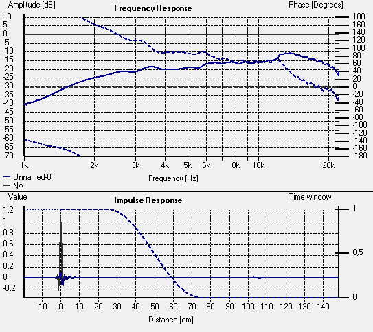
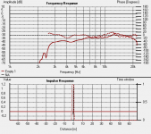
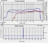
This is a wise piece of advice. AFAIK the tweeter has a very flat frequency response up to 20 kHz, but the measurement shows a rise of 4 dB after 5.5 kHz and a peak of 9 dB at 13.5 kHz. Taking this as reality will be very misleading...🙂
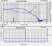
Guys, I'm not sure that baffle step loss is being fully accounted for. Comparing graphs 1 and 2 below, the 1st one (with 1.2mH and 15uF) is only down about 3dB at 800-900Hz from the raw measurement in the 2nd one. I think it's going to need a little more than that. Troels used 1.2mH and 24uF in his Amish revisted, but he also used an LCR filter to pull the peaking at 800-900Hz down as well. Without that contour filter, I think merlin is going to need a higher inductor value. Dickason in his LDC build with it used 3mH without an LCR (his Fxo looks like about 1900Hz though). It's not ideal, but without buying more components, I think merlin should try 2.7mH in series with one of the smaller values he has, like .361, .47 or .56mH stacked on top of it.
merlin, using your measurement of the woofer on baffle without a xo (and splicing its vented response onto it with the full 6dB of baffle step loss), I've come up with the following xo, below, all with parts you already have. Try putting it together and measuring both drivers together with it. Also listen to it to hear how it sounds to your ears. That may be more important at this point if your measurements aren't perfect yet. Adjust the 2nd inductor, L3 and the tweeter resister, R1 to suit your tastes. See how that goes. The last graph is how my sims look but this is with Zaph's measurement of the tweeter - I'm not 100% confident that your's is correct yet, as Dissi has just mentioned too.
merlin, using your measurement of the woofer on baffle without a xo (and splicing its vented response onto it with the full 6dB of baffle step loss), I've come up with the following xo, below, all with parts you already have. Try putting it together and measuring both drivers together with it. Also listen to it to hear how it sounds to your ears. That may be more important at this point if your measurements aren't perfect yet. Adjust the 2nd inductor, L3 and the tweeter resister, R1 to suit your tastes. See how that goes. The last graph is how my sims look but this is with Zaph's measurement of the tweeter - I'm not 100% confident that your's is correct yet, as Dissi has just mentioned too.
Attachments
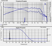
I should mention that in the last graph above, L3 is .56mH with total inductor resistance set to .6ohm (which was just a guess), but that's also with a full 6dB of baffle step. Reality might be a little bit different.
I think merlin should try 2.7mH in series with one of the
smaller values he has, like .361, .47 or .56mH stacked on
top of it.
If Merlin and myself are doing it wrong, so is B&W.
Together with your help and of all the people willing to,
we will get to the bottom of it. You can bet on it 🙂.
3mH is a value which one does not want to use around 2,5 kHz
in our case. It's a fact.
Merlin,
I suggest we decide about conditions of measurements.
I propose something like this and the filter is there to start
for playing around. Make the effort and show the drivers
responses in one graph , so it's easier to watch. Each response
has it's own color code. If your bassmid graph is at for example
-15 dB, so we want the tweeters to be there too. Larger value
caps change the response to go to the left, towards bassmid
and smaller values away from it. So it's pretty straightforward
to find a suitable tweeter filter. The same goes for resistors,
the larger resistance makes the response appear more attenuated .
You want the tweeter rolloff to be similar to the bassmid's, nice
one with neat looking shape. The way things are right now, we want
the XO point to be around 2,2 kHz or so. We will see. We could talk
some more in the evening.
Attachments
Merlin,
now keep the mic on the same spot where you did the 1,2 mH
graph. Record the tweeter response without any filter so we
see how much louder is he than bassmid. Place the mic between
the two drivers if you have not already done that.
Also without 500Hz high pass filter that I use to measure the tweeter with Holm?
Merlin,
I suggest we decide about conditions of measurements.
I propose something like this and the filter is there to start
for playing around. Make the effort and show the drivers
responses in one graph , so it's easier to watch. Each response
has it's own color code. If your bassmid graph is at for example
-15 dB, so we want the tweeters to be there too. Larger value
caps change the response to go to the left, towards bassmid
and smaller values away from it. So it's pretty straightforward
to find a suitable tweeter filter. The same goes for resistors,
the larger resistance makes the response appear more attenuated .
You want the tweeter rolloff to be similar to the bassmid's, nice
one with neat looking shape. The way things are right now, we want
the XO point to be around 2,2 kHz or so. We will see. We could talk
some more in the evening.
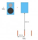
If I understood correctly, I have to place the mic oriented in the mid of the tweeter & woofer and the distance must be 50cm, that I haven't clear is the 0.2m off axis mic position: is due to the fact that I have to take 3 measurements, one on axis and two off axis?
If Merlin and myself are doing it wrong, so is B&W.
Together with your help and of all the people willing to,
we will get to the bottom of it. You can bet on it 🙂.
3mH is a value which one does not want to use around 2,5 kHz
in our case. It's a fact.
What's B&W?
Tweeter without xover, mic positioned in the middle of tweeter & woofer, distance from loudspeaker to mic 50cm.
Attachments

Last edited:
You choose where you want to place the mic. If you were to seat
in sweet spot between a pair of the speakers, then it could be a good
decision to check the meaurements with mic put to the side as pictured.
It is a normal practice to move mic around and see what happens
in general. Stick to one spot for now.
Bowers & Wilkins is a loudspeaker manufacturer.
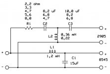
You can start combining values for the tweeter filter as pictured.
Bassmid stays with 1,2 mH and 15uF.
in sweet spot between a pair of the speakers, then it could be a good
decision to check the meaurements with mic put to the side as pictured.
It is a normal practice to move mic around and see what happens
in general. Stick to one spot for now.
Bowers & Wilkins is a loudspeaker manufacturer.
You can start combining values for the tweeter filter as pictured.
Bassmid stays with 1,2 mH and 15uF.
Last edited:
Merlin,
I suggest we decide about conditions of measurements.
I propose something like this and the filter is there to start
for playing around. Make the effort and show the drivers
responses in one graph , so it's easier to watch. Each response
has it's own color code. If your bassmid graph is at for example
-15 dB, so we want the tweeters to be there too. Larger value
caps change the response to go to the left, towards bassmid
and smaller values away from it. So it's pretty straightforward
to find a suitable tweeter filter. The same goes for resistors,
the larger resistance makes the response appear more attenuated .
You want the tweeter rolloff to be similar to the bassmid's, nice
one with neat looking shape. The way things are right now, we want
the XO point to be around 2,2 kHz or so. We will see. We could talk
some more in the evening.
Thanks for the xover I guess there is a lot of combinations to measure? where to start the xover?
Last edited:
You will get a feeling for it in the process. Start by 4,7 ohm;
6,8 uF; 0,36mH; 8,2uF
Record the bassmid with its filter so you know where you stand
and how to manipulate tweeter response further. I'll talk to you
later around 10pm or tomorrow.
6,8 uF; 0,36mH; 8,2uF
Record the bassmid with its filter so you know where you stand
and how to manipulate tweeter response further. I'll talk to you
later around 10pm or tomorrow.
- Status
- Not open for further replies.
- Home
- Loudspeakers
- Multi-Way
- Help for 3 or 4 way loudspeaker