Hi. I need help finishing an Albert Kreuzer's Bass preamp (http://www.albertkreuzer.com/preamp.htm).
I just need to add the two source resistors for the JFETs, and now I see I really don't understand the procedure to select them! I'm using 2N5457 JFETs, thats whats available here. I don't have access to an oscilloscope but I saw he gave instructions to do it without one, but now I just don't get it.
I get the Vgs(off) for the JFET and calculate the drain voltage,then what? Should I put the gate directly at V+ and adjust the source resistor to obtain the calculated drain voltage?
Thanks!
Eugenio
Eugenio,
This is very well explained on the page you listed (at the bottom). If you know Vgs(off), you put a potentiometer in place of R5 (or R10) and change its resistance until you get on the drain of the transistor half of the voltage between V+ rail and Vgs. Then replace the potentiometer with a resistor of similar resistance. Take a look at the example calculation on this page.
Let me know whether it works because I also want to build this preamp.
Marek
Think I got it!
Ok, I went back and took a look at it and I think I finally got it. I was confused because I did not know what the gate signal should be when looking for halfway between v+ rail and Vgs(off), but we dont need a signal at the gate I think. I'l try it.
By the way, Albert Kreuser answered a while ago an e-mail I sent him and suggested playing it by ear. Put trimmers in it and adjust for best sounding setting and then replace with fixed resistors. I'l try this too to see if it changes.
Let you know how it turns out.
Thanks Marek for making me take a second (or fourth) look!
Eugenio
Finally finished the pre-amp, worked great! A lot of range on the tone controls. Really recommend it. Thanks for all your help!
Eugenio
Eugenio
Pics of the build???
im getting ready to embark on this build myself and would like a point of reference
im getting ready to embark on this build myself and would like a point of reference
I did take some pics but I don't have the camera here, I'l try to get it back this weekend and post them here.
Eugenio70 said:I did take some pics but I don't have the camera here, I'l try to get it back this weekend and post them here.
Alright thanks im looking forward to them🙂
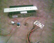
Photo.
Sorry for the low quality, I´m waiting to get my camera back were I have better quality images, and to get a photo of the finished pre-amp.
The power supply is on the left, then the Mid select, and the main PCB. I used a case from a junked satelite receiver, the faceplate is aluminum, painted and silk-screened. In fact, at least 95% of everything including parts, case, etc. is recicled from junked TV's, radios, etc. I only bought the Jfet's, two knobs and the transformer. 🙂
Attachments


Brett said:How do you like the sonics?
I like it a lot, specialy considering my cheap bass which has almost no tone range by itself.
I've used 2 commercial pre-amps from friends and this one is certainly worth it, you wont regret it.
I've built versions of it before and liked it, especially with a higher V PS and rebiassed to suit. Just wondered how you liked it.Eugenio70 said:
I like it a lot, specialy considering my cheap bass which has almost no tone range by itself.
I've used 2 commercial pre-amps from friends and this one is certainly worth it, you wont regret it.
Hey folks,
I'm finishing up this preamp, and I'm running into the same problem. I determined the drain voltage using the 'quick and dirty' method on the site. I assume you go voltage/amperage=resistance, but what amperage do you use? The max the power supply puts out, or measure it off the 'quick n dirty' circuit, or? Or is there a different way to do it?
This is my first attempt at building any audio equipment from scratch, so please bear with me. (I built a bass a few months ago, it worked out well, now I'm doing an amp to match.) Preview:
Attachments


Sorry for reviving an old thread.
I'm confused with the Pre and Post pads. they have their own ground. is it safe to assume that it means that you can select between EQ on or off with it? An EQ bypass(judging from the picture above)? If so how do I wire the SPST? I'm assuming connect both ground to center pole and PRE and POST to the remaining 2 poles...
Nice build BTW barnaclebeau..
jordan
- Status
- Not open for further replies.
- Home
- Live Sound
- Instruments and Amps
- Help finishing Albert Kreuzer's preamp!