I'm Building a White Cathode Follower based headphone amp with 6BL7s on the output. The plate load resistors of one half the tube and the cathode resistors of the other half apparently can be changed to alter the output impedance, but the formula is unknown to me and I can't find a real relation between the values given. Could anyone help me figure out how to adjust for 62 Ohm, and 600?
6BL7 6BL7 6BX7 6BX7
32Ohm 300Ohm 32Ohm 300Ohm
R11 270 270 290 470
R17 140 170 127 205
Thanks for any help, and if anyone can take a minute (right) to explain the process, I'd love to know how this is derived.
6BL7 6BL7 6BX7 6BX7
32Ohm 300Ohm 32Ohm 300Ohm
R11 270 270 290 470
R17 140 170 127 205
Attachments
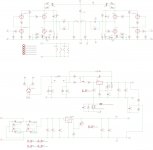
sorry about the data, not sure how to make a readable table . If it becomes necessary I can try again.
Also, please, would it be catastrophic to tie the high voltage center tap to the same ground point as the 5v center tap? I've never used a transformer with a 5 volt CT, so I'm unsure of the best way to proceed.
You want a low output impedance, not one matched to the headphones.
A high output impedance will interact with the headphones and alter their
frequency response, due to the voltage divider action with the non-constant
impedance of the headphones.
If the grounding is not just right, you could get hum. They do both go
to the same circuit ground node, but details matter in circuits like this.
Is this on a pcb, or wired point to point?
Last edited:
That's what I thought, that there is a loose rule 1:10 ratio, but I asked the designer if I could use this PCB (it is a PCB) and use it as a preamp as well as a headphone amp and was told that as it is a White CF, it is a fixed impedance circuit and I would need to couple with a transformer (1:1.5K in my case , but my understanding is that anything over 1:25 starts to mess with frequency response) to actually match the input impedance of the load. I did read that the White CF is not a "one size fits all" circuit, but I'm trying to decipher information that's past my understanding. Thanks for your reply and willingness to help.
...would it be catastrophic to tie the high voltage center tap to the same ground point as the 5v center tap?...
Yes. We do not CT the rectifier heater. (Very old circuits did, but it was not worth the wire, and the rectifier CT is B+, NOT circuit common.)
Driving 32 ohms with small dual triodes is optimistic; 62 little better. The only way to go is wind the tube as hot as it will go, jiggling voltage and current for a best fit. Soft listeners with sensitive headphones may be happy; loud listeners with damped phones may be disappointed. Even 300 ohms is a strain; the odd thing is the WCF "can" do really clean output at this impedance albeit grossly inefficient.
TubeCAD had notes and corrections on WCF design; way too many times in the last 21 years.
Generally speaking, you're not running 1:1 or even maybe 10:1 on 32 ohm headphones with tubes without an output transformer. 300 ohm or higher (HD650 or the high-Z beyers) you'll be fine OTL. If you want to run low-Z OTL your best bet is a NFB loop. I would suggest looking here, read to the bottom:
Aikido Headphone Amplifier
Aikido Headphone Amplifier
Generally speaking, you're not running 1:1 or even maybe 10:1 on 32 ohm headphones with tubes without an output transformer. 300 ohm or higher (HD650 or the high-Z beyers) you'll be fine OTL. If you want to run low-Z OTL your best bet is a NFB loop. I would suggest looking here, read to the bottom:
Aikido Headphone Amplifier
From the article you posted,
"What if you plan on driving both power amplifier and headphones..."
Wellll, I had, and now I'm just plain confused. I've got the board set up to drive low-Z phones, whatever would it make of a 49.9K load? I would think that it would love it. How's about if I've got a 100K potentiometer in-between the input jacks and the board? I've always had a hard time assessing the effect volume controls have. Under those circumstances, would This circuit, as a preamplifier benefit from plugging in the feedback? The sine wave on my scope looks very symmetrical, does that mean that I'm getting optimal push-pull from the amp? Oh well, tomorrow I listen with phones, and I'll make some decisions later. Thanks for the link, it was very informative, even if I'm still trying to hash it all out.
- Home
- Amplifiers
- Headphone Systems
- Help Finding Resistors To Change Output Impedance In Amp?