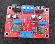
I have a small pre buffer based on 2 x NE5534's (Pic Attached)
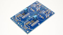
I also have dual supply regulator boards from here based on TPS7A4700 (Pic Attached)
I have no idea how to work out how small a transformer I can get away with, this is the one that I have boiled it down too:
10-5852 | RS Pro 12VA 2 Output Chassis Mounting Transformer, 12V ac | RS Pro
but can I go any smaller?... as I'm limited to chassis real estate!
I know that I can attach each of the dual secondaries to its own half of the PCB board, not centre tapped so each half of the board will get 12ac.
This will be rectified to 1.414 * 12 = 16.9V
I know I will drop a few volts to diodes and caps but can I get away with less voltage?
I calculate 6VA on each 12V secondary as giving me 500mA for each supply voltage +/-15V
Do I need 15V? do I need 500mA? or is my maths all wrong too!!
I would be so grateful to anyone who may be able to find me a smaller transformer, don't think I can go PCB mount as I wouldn't know how to mount it,
Stuart
Attachments
You need split supply, +15V, 0, -15V.
Your regulators are both positive.
You need 1 positive and 1 negative regulator.
TPS7A33 series if you wish to use this type of regulator.
TPS7A4700/TPS7A3301 Ultralow-noise LDO Voltage reg.w/Dual Polarity PSU PCB TypeB | eBay
Or use the popular LM317/LM337. See Elliott Sound Products P05B which also explains how a single AC supply can be split.
If chassis space is limited, use a wallplug transformer.
Your regulators are both positive? I think that's only relative to where you decide to split the voltage, the idea here is to tie the negative from one regulator to the positive of the other regulator thus splitting the rail. This is what I will be doing but I'm still confused about how big my transformer needs to be, power Wise.
Also interested to know if this floating ground will effect the fact that audio signal passing through the preamp will be referenced to earth ground....
Also interested to know if this floating ground will effect the fact that audio signal passing through the preamp will be referenced to earth ground....
Your regulators are both positive? I think that's only relative to where you decide to split the voltage, the idea here is to tie the negative from one regulator to the positive of the other regulator thus splitting the rail. This is what I will be doing but I'm still confused about how big my transformer needs to be, power Wise.
Also interested to know if this floating ground will effect the fact that audio signal passing through the preamp will be referenced to earth ground....
If you can use a negative polarity regulator, it's probably easier - however I've used and have seen dual positive regulators used with the positive of one tied to the negative of the other to create a 'ground' - this is fine (a few Gainclone regulated PSU's are designed this way).
That being said, CT transformers seem to be a bit cheaper and easier to come by and you can buy those cheap dual polarity boards from ebay - I just grabbed a =/- 12v supply for about $20 total including the transformer. The output current will depend on what they're driving, but I wouldn't expect you'd be able to push much more than 40mA through each - you could possibly get away with a much smaller transformer.
I calculate 6VA on each 12V secondary as giving me 500mA for each
supply voltage +/-15V Do I need 15V? do I need 500mA?
If we assume 15VDC output, then 15VAC minimum input voltage to each PS board
is needed for proper operation, to allow for diode drops, regulator drop, and low line.
Very little load current is needed, so choose the smallest VA size transformer with
two 15VAC secondaries. For example: http://uk.rs-online.com/web/p/chassis-mounting-transformers/0503972/
Last edited:
I'd use an Antek AN-0115 - 10VA 15V Toroidal Transformer. Only $10 each plus shipping in the U.S. Toroids are always significantly smaller than EI core trannys. Plus, they radiate very little AC field.
When you rectify and filter the 15VAC, you'll get about 20VDC, which is perfect for + and - 15 volt regulators. Put a 1M ohm R across the primary (to dissipate the stored charge in the core when turned off), and a .01uF 1kV cap across the primary and secondary (to block incoming Rf and switching noise from the rectifier diodes). Put 0.1uF caps across the large electrolytics in the power supply (so regulator chips see 0 ohms well into the mHZ), and from each PS to Gnd within an inch of each opamp (for phase margin predictability). Tie all power supply grounds together, then run a wire from that junction to the star center Gnd for everything else (for minimal hum). Tie that to the chassis in only one place (so no Gnd loops).
When you rectify and filter the 15VAC, you'll get about 20VDC, which is perfect for + and - 15 volt regulators. Put a 1M ohm R across the primary (to dissipate the stored charge in the core when turned off), and a .01uF 1kV cap across the primary and secondary (to block incoming Rf and switching noise from the rectifier diodes). Put 0.1uF caps across the large electrolytics in the power supply (so regulator chips see 0 ohms well into the mHZ), and from each PS to Gnd within an inch of each opamp (for phase margin predictability). Tie all power supply grounds together, then run a wire from that junction to the star center Gnd for everything else (for minimal hum). Tie that to the chassis in only one place (so no Gnd loops).
- Status
- This old topic is closed. If you want to reopen this topic, contact a moderator using the "Report Post" button.