Just looked thru my parts and found some LEDs (see links below). Will any of these work?
a. SLX-LX3054YC Lumex | Mouser
b. SSL-LX5093LBI-SRD Lumex | Mouser
c. SSL-LX305D4GD Lumex | Mouser
d. SSL-LX3054ID-5V Lumex | Mouser
a. SLX-LX3054YC Lumex | Mouser
b. SSL-LX5093LBI-SRD Lumex | Mouser
c. SSL-LX305D4GD Lumex | Mouser
d. SSL-LX3054ID-5V Lumex | Mouser
We have music played thru a speaker. But, a couple of items need help:
BIAS on C3g:
Measured from Anode to ground without any B+ and with filament voltage only, the voltage is -2.2Vdc
Measured from Anode to ground with B+ and filament voltage, the voltage is +2.3Vdc
Measured from LED positive (+) leg to ground without any B+ and with filament voltage only, the voltage is +0.6Vdc
Measured from LED positive (+) leg to ground with B+ and filament voltage, the voltage is +157Vdc
60hz HUMMMMM
There is 0.34Vac (yes, 0.34Vac huge) hum. Of course, loudly audible thru speakers. The grounding scheme is as follows:
lowest voltage parts are grounded to the bus bar at the farthest point away from earth/chassis ground. As the part voltages increase, the voltage bus bar (12AWG bare copper wire) connection points get closer to the earth/chassis ground. There is no chassis at this point, other than the metal (steel) back panel which is tied to the earth ground and bus bar.
Thoughts?
Thanks
found some LEDs
As wrote earlier in another topic, I use two series IR LED.
BTW the correct up-to-date schematic is the starting point (you sketch different schematics in different topics).
C3g is IDHT tube, so potential difference between cathode and filament almost indifferent (below certain voltage).
As far as excessive B+ When I want to figure out what transformer to use I take one side of it times 1.2 so for a 500-0-500 (500 * 1.2) = 600V approximate of course if I needed 498 I'd probably look for a 425-0-425 (425 * 1.2) = 510V or something like that.
mark02131,
For a full wave tube rectified B+, these are the general factors:
For a Capacitor Input B+ filter:
1/2 primary winding: AC VRMS x 1.414 = Peak Volts (the rectifier sees this peak voltage).
Peak Volts - Rectifier's rated voltage drop = rectifier output Volts.
DCR of primary x voltage step up ratio + DCR of 1/2 secondary = DCR total
DCR total x loud current = DCR Voltage drop
rectifier output volts - DCR V drop = DCV at capacitor input B+ filter
For a Choke Input B+ filter, use AC VRMS x 0.9, and subtract the rectifier rated voltage drop.
AC VRMS x 0.9 - rectifier drop = rectifier average voltage out.
DCR of primary x voltage step up ratio + DCR of 1/2 secondary = DCR total
DCR total x loud current = DCR Voltage drop
rectifier (average) output volts - DCR V drop = Choke output volts
So many people use the power supply calculation software programs.
I just do my own by longhand calculations.
But if you do not know the primary DCR, primary to secondary step up ratio, the 1/2 winding secondary DCR, the Choke DCR, the load current of your amplifier, and the tube rectifier voltage drop at the load current your amp will put on the B+, you will never know what B+ you will get.
You will not even be close.
Last edited:
Mark02131,
You want 498VDC
500V B+ with Capacitor Input B+ filter.
Primary DCR = 10 Ohms
Primary to Secondary Step Up ratio is 1:3.25
1/2 Secondary DCR = 32.5 Ohms
Effective DCR total = 42.5 Ohms
120VAC in = 390Vrms out
Rectifier drop = 50V
390V x 1.414 = 551 Vpeak
551Vpeak - 50V = 501V
If the amplifier's total B+ load is 70mA, the total DCR voltage drop is 0.070 x 42.5 Ohms = 3V
501V - 3V = 498V (approximately, but at least very close to that).
Wow, that worked out!
Do not forget to use a B+ bleeder resistor.
Safety First!
Prevent the "Surviving Spouse Syndrome".
And the total load on the B+ for a 2 stage amplifier is typically input stage load, output stage load, and bleeder resistor load.
Forget any factor of all the above discussion, and you will get a different B+ voltage.
So many variables, power transformer, rectifier tube . . .
and one very important factor: the mains power voltage (mine varies from 117V to 123V).
If you get close to your desired B+, I hear the Tobacco Fairy puts a Cigar under your pillow.
And, if you prefer a choke input filtered B+ (I do), use a power transformer that has 1.414/0.9 = 1.57 times higher secondary voltage than for a capacitor input filter.
All other things being equal, the transformer and the rectifier tube will both run much much cooler (oh, the rectifier voltage drop will be slightly less).
Let us know what kind of amplifier you are planning, post a schematic, etc.
Have fun!
Last edited:
banpuku,
Wow!
so much hum.
Try shorting across the interstage transformer secondary . . .
Now, how much hum?
Magnetic Steel (not stainless, not aluminum) chassis?
Interstage transformer close to power transformer?
Interstage transformer close to B+ choke?
Did you align the interstage transformer coils at right angles (90 degrees), versus Both
the power transformer and choke coils.
Wiring connections, etc. that creates bad ground loops?
Any of the above?
Hum, Hum Hum.
Fix that hum (but with as much as you have, I do not have to tell you).
My latest amplifier is built on an old steel chassis, that I use to test a new circuit idea.
It sounds great, except . . .
I am very disappointed with the hum, I am getting 1mV hum, nothing I can do because of the [magnetic] steel chassis.
Most of my amplifiers have 100uV or less hum. In order to get hum that low, you have to pay attention to all details of the many causes of hum.
Last edited:
banpuku,
Wow!
so much hum.
Try shorting across the interstage transformer secondary . . .
Now, how much hum?
Magnetic Steel (not stainless, not aluminum) chassis?
Interstage transformer close to power transformer?
Interstage transformer close to B+ choke?
Did you align the interstage transformer coils at right angles (90 degrees), versus Both
the power transformer and choke coils.
I re-routed B+ wires and bypass caps/resistors. This reduced the hum to 0.245V from 0.37V. I am going to do more on this front and see if it helps.
I shorted the secondary of the IT and it reduced the hum to 0.177V from 0.245V.
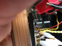
I moved the IT so it is far away from everything (see photos). Also tried to rotate the IT in many different rotational positions (all 3 - axis) and it did not help. I have a ISO Tango NC-20F II and it is shielded very very well, as far as I can tell. BTW: The ISO Tango product is first rate from a build and aesthetics perspective.
Also tried moving and rotating the PT in many different rotational positions (all 3 - axis) and it did not help. I was not able to move it far far away (like I did with the IT), as it is wired to the back panel for AC and ground. BTW: teaser comment, the Monolith Magnetics PT, OT and Chokes are exceptional. Talk about solid. No mechanical hum. More to come.
Tried re-routing AC heater wires. No help. See photo for heater twisted tightness (yellow wires).
So, we have it down to 0.177V assuming we short the IT secondary. Any other thoughts?
Pat
Attachments

Hey pat. I guess this is the new thread now. right? More than one thread is confusing.
Also, why not share your latest schematic? This will help us solve the hum...
Ian
Also, why not share your latest schematic? This will help us solve the hum...
Ian
banpuku,
Are you using AC filaments on the 45B?
Yes?
When you short the interstage transformer, and you still get 117mV of hum, the AC filament circuit is where your hum is coming from (unless your B+ has way too much ripple.
Does the 45B have a center tap filament (3rd filament connection pin)?
Please post the complete schematic of the 45B filament power supply, how it connects to the 45B filament, and all of that part of the amplifier circuit.
Last edited:
let's take the conversation over to the other thread. Follow this link. It will have the most recent schematic.
Pat
Help please: Bias and hum
Pat
Help please: Bias and hum
Mark02131,
You want 498VDC
500V B+ with Capacitor Input B+ filter.
Primary DCR = 10 Ohms
Primary to Secondary Step Up ratio is 1:3.25
1/2 Secondary DCR = 32.5 Ohms
Effective DCR total = 42.5 Ohms
120VAC in = 390Vrms out
Rectifier drop = 50V
390V x 1.414 = 551 Vpeak
551Vpeak - 50V = 501V
If the amplifier's total B+ load is 70mA, the total DCR voltage drop is 0.070 x 42.5 Ohms = 3V
501V - 3V = 498V (approximately, but at least very close to that).
Wow, that worked out!
Do not forget to use a B+ bleeder resistor.
Safety First!
Prevent the "Surviving Spouse Syndrome".
And the total load on the B+ for a 2 stage amplifier is typically input stage load, output stage load, and bleeder resistor load.
Forget any factor of all the above discussion, and you will get a different B+ voltage.
So many variables, power transformer, rectifier tube . . .
and one very important factor: the mains power voltage (mine varies from 117V to 123V).
If you get close to your desired B+, I hear the Tobacco Fairy puts a Cigar under your pillow.
And, if you prefer a choke input filtered B+ (I do), use a power transformer that has 1.414/0.9 = 1.57 times higher secondary voltage than for a capacitor input filter.
All other things being equal, the transformer and the rectifier tube will both run much much cooler (oh, the rectifier voltage drop will be slightly less).
Let us know what kind of amplifier you are planning, post a schematic, etc.
Have fun!
Thanks!
I'll start using the correct calculations to get my power supply voltages. It sure will get me closer to the ideal voltages
- Home
- Amplifiers
- Tubes / Valves
- Help: Excessive B+