About a month ago I posted about how I was making high voltage umbilical cables because I want to make a PSU that is separate. One mechanical advantage of that form factor is to make a truly very heavy choke input tube rectifier (enclosed tube) PSU LCLC for use with maybe a few different "old school" projects. To get all that heavy iron and magnetic fields out of the amp which can now be compact with the big PSU on the lower shelf or floor. In todays market what chokes might be best for choke input? I'm thinking Hammond 193MP potted, 10H, 300ma, 63 ohm model (10.5 lbs heavy!). My intention is to make a fine, old school, PSU, with umbilical that I can re-use across a few different amps I want to make. A PSE 300B, an 807 Amp, a 6L6 family PP amp (compatible with sweep tubes), and others all getting their raw power from this PSU, plug and play. I'm talking a PSU that is a boat anchor here, suggestions on the making of a boat anchor PSU would be appreciated. Toroid power or EI? I'm thinking 300ma output, fixed voltage TBD or perhaps a way to buck/boost series/parallel the power transformer to obtain 2 or 3 different voltages (with 2 or 3 different circular output connectors)? What would be a good 'set" of maybe 2 or 3 voltages to target (600V or less)? Lots of things I need to consider and hoping to tap into folks knowledgeable in big old school PSU's. Duplicating it for a worthy dual mono project may be in the future too, dual boat anchors.
Last edited:
If weight and size aren't issues, install a variac on the primary of the power plate transformer to dial in whatever voltage you need. I'd also install meters for voltage and current and separate filament/heater transformers.

A choke input supply must have a minimum load current for proper operation. The output voltage in a choke input supply is usually 0.9 to 1.1 times the applied AC voltage as long as it under load. This voltage will rise toward 1.4 times the AC supply if the load is removed. I have long ago forgotten how to figure out this "critical current" but I'm sure that Google or an old ARRL handbook will have a good explanation.make a truly very heavy choke input tube rectifier (enclosed tube) PSU LCLC for use with maybe a few different "old school" projects.
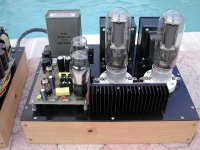
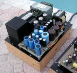
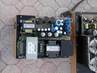
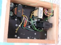
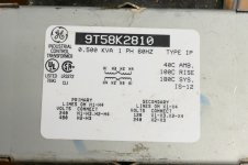
I tend to use whatever transformers I can find or get cheaply. I have been known to mix EI and toroids in the same amp. The 845SE amp used a separate power supply and amp since an all in one design would be too large and heavy. The power supply used a wide variety of "stuff" including a 500 VA 480-to-120-volt industrial control transformer (top of picture) hooked up backwards feeding a voltage doubler made with 5AR4 tubes to get 1100 volts at 150 to 200 mA. These transformers used to be real cheap on Ebay. The shipping cost more than the transformer. The black cube is a military surplus choke rated for 250 mA. It was not rated for use at over 1KV so it is in the negative leg of the 1000 volt supply.
The Allied 6K7VG powers the driver board which is a home cooked prototype of what became the original TSE board. The smaller Allied 6K80VBR is for heater power. It has two 12 volt 4 amp windings that are rectified and filtered to make independent 10 volt 3.25 amp DC supplies for the 845 output tubes.
There are two transformers and a choke hidden under the deck. The Allied unit runs the only PowerDrive board I ever made (on amp chassis with heat sink). The black ugly transformer lights up the 5AR4's in the doubler. It came from something I stripped for parts. It had a 2500 volt isolation rating which is needed for the 1100 volt supply. The choke is used in the 450 volt supply for the TSE board. It might be obvious from all the extra holes that this amp went through a lot of revisions. The Umbilical connectors are Cinch Jones connectors. They used to be available from DigiKey when I built this amp about 20 years ago.
This amp put over 500 watts of excess heat into my 10 X 10 foot room in Florida to make 30 WPC in A2 which limited it's use. By the time I got it set up after moving North I had discovered sweep tubes and UNSET so the amp got sold at the Dayton Hamfest a few years ago. The buyer just wanted the OPT's and some of the output tubes.
a 6L6 family PP amp (compatible with sweep tubes)
Remember that 6L6 types need a screen grid supply that produces almost as much voltage as the plate supply. Most TV sweep tubes will need a screen supply in the 125 to 200 volt range. You will need both for a universal supply.
My first and by far the heaviest boat anchor supply was real simple. It used two Variacs, two of those 480 volt industrial control transformers, one 120 / 240 volt to 24 volt industrial control transformer, four large solid state bridge rectifiers, two chokes and a bunch of caps. I put it in a rack mount chassis and managed to get on to my workbench where it stayed for a few years. Each supply was simply a transformer feeding a bridge that fed a CLC filter. The BIG Variac fed a pair of 480 volt transformers hooked up backwards (120 to 480 volts) which each fed its own bridge / CLC filter. This provided two independent 0 to almost 600 volts supplies which were controlled by the same Variac. These could be wired in parallel, series, or used independently for my brief and sometimes explosive fascination with OTL circlotrons. The small Variac fed the small industrial control transformer which had two 24 volt windings. This made a pair of 0 to about 30 volt supply for heaters and stuff that ran on 12 volts. It was only filtered by a pair of real big caps. This was simple, cheap but deadly and made for some serious fireballs and scattered parts as there was nothing to limit the short circuit current except the 15 amp breaker for the whole bench and a line fuse that never blew. An experiment involving a pair of 6LW6's one of my 80 VA guitar amp grade OPT's and the two 0 to 600 volt supplies wired in series set the OPT on fire when my audio dummy load made with parts from Radio Shack went open somewhere past 150 watts. It burned a big, charred spot in my workbench which was expertly crafted from an old door. I eventually collected enough variable bench power supplies to do everything except circlotrons, so the big boat anchor was dismantled.
I gave most of my big iron to friends and finally to a metal scrapper when I left Florida and had to move all the stuff that I wanted to keep. An unexpected event turned our planned migration into a hasty exit.
I still have one of those 480 volt industrial control transformers from the dismantled supply. It is exactly like the one in the amp. It has been in the same spot on a shelf since I moved here 10 years ago. You can have it if you want it. Some of these can be noisy. These are partially potted, so they are quiet. They go get quite warm when run at full load. PC board in background is 9 inches wide and those are 6L6GC's and 12AX7's for a size comparison. I can ship or bring to the Dayton Hamfest. My guess at the weight is about 15 pounds. I also have a box full of Variacs here somewhere.
Attachments

If weight and size aren't issues, install a variac on the primary of the power plate transformer to dial in whatever voltage you need. I'd also install meters for voltage and current and separate filament/heater transformers.
Yes! This is why I love this forum. I forgot that I own four small "theater lighting" variacs in my stash (back when theaters used incandescent lighting). Weight is not an issue. The whole thing will be inside an enclosed aluminum box (brick), rectifier, iron, etc. I can easily mount a variac control on the backside maybe with some form of locking knob so it cant be accidentally turned (photo below). These variacs are 60mm deep and 75mm in diameter, half the size of the coffee cup shown. 2.5A rated. Just thought of another thing, electrolytic capacitors will be in series with balancing resistors so they can withstand voltages. First capacitor after the choke will be a big WIMA MKP film, I have some 900V 100uF film caps waiting for a project.
Thanks!
A choke input supply must have a minimum load current for proper operation...
Thanks George, lots of important info here, wow. Choke in the negative rail, I'll have to remember that too. I know I'm not going to venture over 600V. Unfortunately Dayton is "iffy" this year, it is right up against another planned vacation. I'm trying to "use up" iron I have but appreciate the offer for more! I want to get choke and xformer iron cleaned out of a basement closet and moved into useful and "finished" enclosures, even if I don't have an exact purpose yet. At least the stuff will be mounted into enclosure(s) I can tweek. Iron takes up the most room in the house, hard to store, hard to move, by making a few big PSU's I dont have to have this stuff waiting for the long process of a project to maybe use it.
My PSU boat anchors will not have any open/exposed components, I want everything fully enclosed in an aluminum box, somewhat commercial looking, which I'll machine myself. I really liked the "Border Patrol" 300B amps I heard at AXPONA which use separate PSU's, they look like very clean "aluminum bricks" under the amp which has more of a traditional form. The photo below is what I'm looking to do, the two aluminum "bricks" on the bottom shelf are dual choke-input power supplies, fully enclosed, the amp above it to the left is a PSE 300B running off the PSU's. I like the "look" of an enclosed PSU with a traditional amp form factor.