what about this?
Sure! you need two tubes though. You can direct couple the first stage to the follower, and then use a CCD for the follower load. That way, you delete a coupling capacitor (usually a good thing).
Last edited:
Will that work? The current mirror will force equal current through both anodes. Therefore, any feedback to tube section B will be isolated from effecting tube section A.
I think you want independent current sources for each anode.
I think you want independent current sources for each anode.
Will that work? The current mirror will force equal current through both anodes. Therefore, any feedback to tube section B will be isolated from effecting tube section A.
I think you want independent current sources for each anode.
It feeds back through the joined cathodes.
Nice! 🙂
You can make a simple -8 volt DC or so negative supply from the 6.3 volt AC heater supply. You'd need a bridge rectifier, a capacitor and just ground the + side of the rectifier. It's only about 2mA for this anyway. simple.
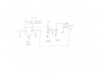
My idea for the input stage comes from something like the attached file. I may have made a mistake in what I shared but that's the basic idea. The document that it came from is here:
http://ocw.mit.edu/courses/electric...009/lecture-notes/MIT6_012F09_lec20_loads.pdf
I have not read it all yet.
Q3 and Q4 are the triode.
http://ocw.mit.edu/courses/electric...009/lecture-notes/MIT6_012F09_lec20_loads.pdf
I have not read it all yet.
Q3 and Q4 are the triode.
Attachments
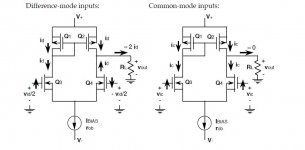
Yeah, maybe I have the connections a little bit off on the input stage. See here:
The SOHA II Headphone Amplifier
Then again, maybe not. The first stage is supposed to be inverting.
The SOHA II Headphone Amplifier
Then again, maybe not. The first stage is supposed to be inverting.
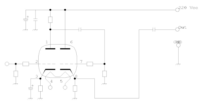
Some important points. The 12AX7 triode lacks the ability to drive g1 of triode wired 6L6s. 🙁 CCS loading 'FQ7 sections will push the gain up to nearly the full μ of 20 and bypass caps. on the cathode resistors can be omitted. 🙂 The 1045S previously mentioned is fine for the CCS here.
BTW, the place for a CCS in a differential gain block (LTP) is in the tail. Do not CCS load the anodes, especially if a tail CCS is used. Choke loading LTP anodes is fine.
BTW, the place for a CCS in a differential gain block (LTP) is in the tail. Do not CCS load the anodes, especially if a tail CCS is used. Choke loading LTP anodes is fine.
This data sheet may be helpful http://www.retrovox.com.au/STC807.pdf The 807 and 6L6 are from the same family of tubes, so the data will be valid.
I have uploaded STC 6L6G application report as well. 23 pages.
See http://retrovox.com.au/STC6L6G.pdf
David
BTW, the place for a CCS in a differential gain block (LTP) is in the tail. Do not CCS load the anodes, especially if a tail CCS is used. Choke loading LTP anodes is fine.
I'm curious, can you explain why CCS is a bad idea for the loads on the LTP? It's apparently done in the tube world and it's common in the solid state one.
I agree the best place for the CCS is in the tail of the LTP.
I can see potential problems if the CCS drift and you get serious shift in your quiescent voltages. The CCS in the tail can fight the CCSs in the plates in a way. But if you shunt the CCS with a high value resistor this shouldn't be a problem, or make sure eventual drift is common and tracks.
Btw Maurizio, you are aware using b+ of 240volts will produce a very low output power? Usually these tubes are used with > 400V. It will work, but you'll have loudness troubles.
I can see potential problems if the CCS drift and you get serious shift in your quiescent voltages. The CCS in the tail can fight the CCSs in the plates in a way. But if you shunt the CCS with a high value resistor this shouldn't be a problem, or make sure eventual drift is common and tracks.
I don't know what others have done about this possibility, or even if it's a serious problem. I wish I knew more about circuit design.
- Status
- Not open for further replies.
- Home
- Amplifiers
- Tubes / Valves
- help designing 6L6G S.E. amplifier