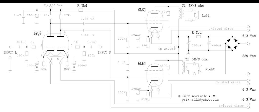
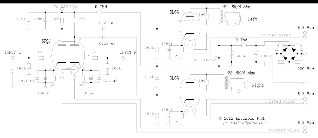
I am designing a stereo tube S.E. amplifier.
This amp uses one 6FQ7 (driver) and two 6L6G (triode connection).
I am looking for help, comments, suggestions.
Thank's for your help.
Maurizio
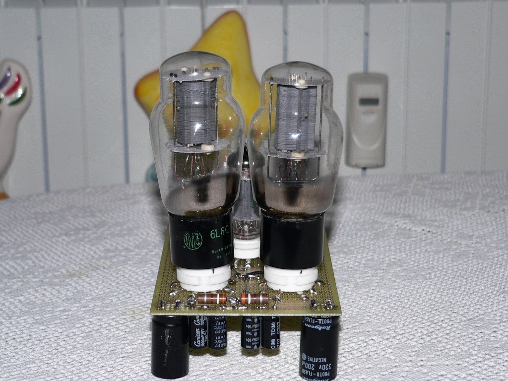
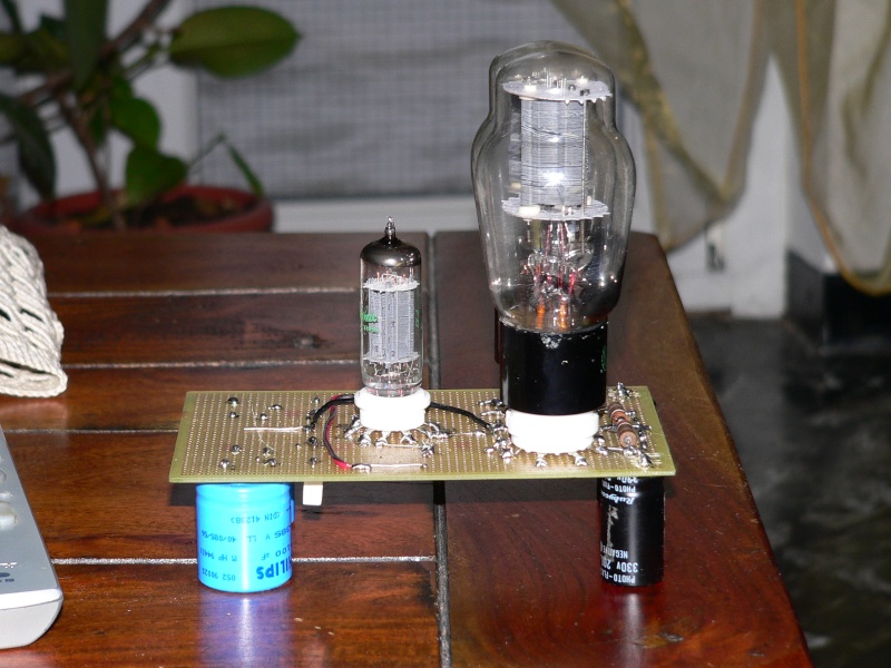
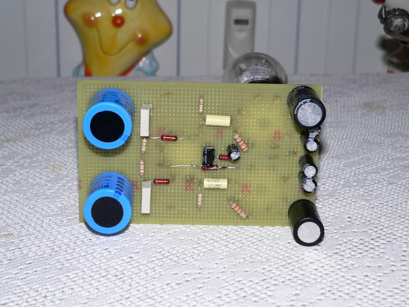
Early prototype:
This amp uses one 6FQ7 (driver) and two 6L6G (triode connection).
I am looking for help, comments, suggestions.
Thank's for your help.
Maurizio
Early prototype:
Last edited:
6L6s need a fair amount of drive voltage. I don't think a single 'FQ7 section is going to get the job done, unless a line stage with gain is employed.
Study of the 6L6 data sheet might be beneficial.
A nice thing about the 6L6 is that it is safe to use in a positive g1 current configuration. Class "A2" operation will let you squeeze more power out of triode mode. Check out Tubelab's PowerDrive
Study of the 6L6 data sheet might be beneficial.
A nice thing about the 6L6 is that it is safe to use in a positive g1 current configuration. Class "A2" operation will let you squeeze more power out of triode mode. Check out Tubelab's PowerDrive
Given the drive requirement of 20V peak in class A triode operation I think the 6FQ7 is doable but on the edge.
Drive = 20V peak
Given a mu of 20, and fully bypassed cathode resistor one can expect a gain of around Av = (mu * Ra) / (Ra + ra) with Ra=27K and ra = 7000 (guestimation from data sheet) gives Av= 15.88
So it should be acceptable as long as his input device can provide 1Vrms drive or better.
The low plate resistance of the 6FQ7 should allow for some entry into A2 operation given that his drive input is sufficient to achieve A2.
I'd look at the 100K grid resistor and see if it can be increased which will allow for a smaller coupling cap value. (cathode bias up to 500K)
http://scottbecker.net/tube/sheets/127/6/6L6GC.pdf
I recommend dropping the first 400uF cap to a lower value like 100uF and increasing the second cap value to 330uF or better. This will increase your conduction angel of the rectifier bridge and improve efficiency. It will also give a better filter for the 120Hz noise you need to suppress in a SE design.
Use low noise diodes and bypass with either 10nF caps or 10nF caps with 4.7r series resistors. Do not use 1N4007 without bypass snubbers and or ferrite beads.
I presume he is requesting help with the TBD resistor values. If you want 250V on the plate at 40mA (wrong cathode resistor, but data sheet bogie) you need around 625 ohms for the resistor between the first and second filter caps. This assumes you only get 1.25* 220VAC as the rms voltage at the first cap.Pd = 25*.04=1W so use a 3W or so resistor.
250-180V = 70V drop across the dropping resistor to the input tube anode resistor. Given you want 50% voltage drop in the anode resistor this gives 90V, dividing by the anode resistor value gives 3.33ma bias current (haven't checked the anode resistor value vs bias).
70V at 3.3mA is 21K.
Pd = 2.3W so use a 5W resistor.
Last edited:
This data sheet may be helpful http://www.retrovox.com.au/STC807.pdf The 807 and 6L6 are from the same family of tubes, so the data will be valid.
Using a 470K grid resistor you can drop to a .056uF coupling cap and still achieve a 6Hz -f3. 0.022uF and 470K would be 31.6Hz.
Using a 470K grid resistor you can drop to a .056uF coupling cap and still achieve a 6Hz -f3. 0.022uF and 470K would be 31.6Hz.
Did you take into account source impedance... the 27k plate resistance ??
Chris
Based on your suggestions, this is the modified schematic:
Note: I increased the plate voltage of 6FQ7 and I removed the input coupling caps.
Any other improvement, suggestion?
Thank's.
Maurizio
Note: I increased the plate voltage of 6FQ7 and I removed the input coupling caps.
Any other improvement, suggestion?
Thank's.
Maurizio
Last edited:
Did you take into account source impedance... the 27k plate resistance ??
Chris
No, I did not, but if you want to do that combine with the anode impedance for full analysis and you get:
f = 1/(2*pi*(470K + (27K||ra))*0.022uF)
27K||ra ~= 27K||7700 = 5.99K
f=1/(2*pi*(470K + 5.99)*0.022uF)
f=15.198Hz
I made a mistake in the original calculation, it should have been 15.39Hz, not 31.6Hz.
15.39Hz vs 15.198Hz is noise compared to the tolerances of the components.
The difference due to the anode impedance is negligible.
Last edited:
6L6s need a fair amount of drive voltage. I don't think a single 'FQ7 section is going to get the job done, unless a line stage with gain is employed.
Study of the 6L6 data sheet might be beneficial.
A nice thing about the 6L6 is that it is safe to use in a positive g1 current configuration. Class "A2" operation will let you squeeze more power out of triode mode. Check out Tubelab's PowerDrive
Replace the 27Kohm load resistors with constant current sources and the triode will have more gain.
Replace the 27Kohm load resistors with constant current sources and the triode will have more gain.
I have two TL431 shunt regulators.
May I use them?
Vref = [FONT=Nimbus Roman No9 L, serif]2,495 V fixed
V max on TL431 = [/FONT][FONT=Nimbus Roman No9 L, serif]36 Vcc
[/FONT]
Last edited:
And be more linear.
Yup. This can be done a few different ways. You can use a jeft, mosfet, bipolar or a constant current diode (also called a current regulating diode). Most of the CCD's are good for up to 100 volts, but can be placed in series for higher voltages. CLD's are easy to use because they are calibrated in current. If you have enough voltage across the 27k resistor, you can use a tube also.
Last edited:
I have two TL431 shunt regulators.
May I use them?
Not sure. don't have time to read up on them.
A constant current source for each triode will also increase the PSRR for the stage.
Oh, I didn't have picture at the time. Yeah, that looks good. I'm not sure about noise though. You may want to bypass the TL431 with a small 0.1uF capacitor to ground.
OK, now you made me look up this part... I see it's low noise already. The transistor in that circuit has to be able to handle the voltage drop of course.
Last edited:
I have two TL431 shunt regulators.
May I use them?

No, the TL431 can't handle the high voltages.
There are lot's of CCS possibilities. Gary Pimm has a nice website about it: Welcome to Gary Pimm's DIY Page
But you can get away much easier when you use a tube with higher µ like 12AT7/ECC81, 5751, 12AX7/ECC83 etc.
The LT431 can not stand the voltage.
You can build a discrete two transistor current source (one has to be rated greater than your B+), or use a single device like the IXP10M45S, DN2540, or SILND150.
Pete Millet has a nice discussion here:
Current Source
And there are several threads on this group.
DN2540 discussion:
http://www.diyaudio.com/forums/tubes-valves/106202-dn2540.html
Discrete Discussion:
http://www.diyaudio.com/forums/tubes-valves/156684-ccs-transistor-choices.html
Use search to find them.
All you need is a resistor and a triode if you've got enough B+, but of course you can get a lot more fancy here.... mu followers, cascoding, etc...
I would use two input tubes and make them differential amplifiers with current mirror loads, constant current tails, and provide negative feedback to the - side of the differential from secondary of the transformer... but that would make me a heretic!
I would use two input tubes and make them differential amplifiers with current mirror loads, constant current tails, and provide negative feedback to the - side of the differential from secondary of the transformer... but that would make me a heretic!
No, the TL431 can't handle the high voltages.
There are lot's of CCS possibilities. Gary Pimm has a nice website about it: Welcome to Gary Pimm's DIY Page
But you can get away much easier when you use a tube with higher µ like 12AT7/ECC81, 5751, 12AX7/ECC83 etc.
I think that using ECC83 instead of 6FQ7 is the easier and simpler way to increase gain.
Thank's again to all for your suggestions.
It looks to me like it is almost finished. Power it up and try it the way it is. You can always change it later.
I think that using ECC83 instead of 6FQ7 is the easier and simpler way to increase gain.
Thank's again to all for your suggestions.
If you do that then you have just increased the output impedance of your input stage making it less likely that the triode strapped 6L6 will be driven cleanly. I'm not sure that's a good plan. The ECC83 is a high mu triode (12AX7) vs. the medium mu 6FQ7.
If you've got enough bias on the 6FQ7 it'd be better to add a gain stage before it.
- Status
- Not open for further replies.
- Home
- Amplifiers
- Tubes / Valves
- help designing 6L6G S.E. amplifier