Hello
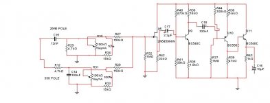
The circuit below is meant to do a simple BASS/TREBLE adjustment. It works fine on the simulator. However on the board it oscillates at about 95KHz-100KHz with a funny looking, not sinusoidal shape at +/- 2 Volts! I have tried to replace the FET with a simple transistor in common collector - again exactly the same issue. If I disconnect the FET from the following circuit, and instead put a tone generator onto the rest of the circuit, then that works fine. The weird effects happen when the tone + FET stage is connected to the rest of the circuit.
Any help appreciated!
Attachments
It works fine on the simulator.
Er, no it doesn't. 'Cos when I simulate (in my head) moving the wipers of both those pots to the earthy end, then you have no signal at the FET input i.e. it's connected to ground by 2*150K resistors and the input signal is grounded by the 2 * 100k pots.
Use a proper Baxandall or other tone control prototype and nomograms to design a conventional filter and use an opamp or two for some gain if necessary. Although it's probably heresy to say so here, anytime you've got 4 active discretes you should be thinking opamp, if only in terms of component count.
w
Hi, it is meant to cut off completely, it is for a guitar amp.
The puzzling thing is the oscillations at 95KHz (or thereabouts).
I will go experiment some more (on the real circuit).
The puzzling thing is the oscillations at 95KHz (or thereabouts).
I will go experiment some more (on the real circuit).
You have four stages, cap coupled, with associated phase shifts. I did not take the time to calculate the gains, but it is not puzzling that it oscillates. All you need is a little bit of signal to leak from output to input in the right phase. Use a jfet opamp, keep the layout tidy, roll off the HF gain somewhere.
w
w
I have added decoupling caps (do not show in diagram).
The very puzzling thing is that when i replaced the jFET with a transistor, the oscillation is still there.
This may be what wakibaki said: a leak from the output to the input, a gain of 100, and no HF rolloff other than paracitic capacitances.
Tomorrow morning I will try to roll off the HFs and see what happens.
- Status
- Not open for further replies.
- Home
- Amplifiers
- Solid State
- Help debugging this circuit