help customize "slow turn-on" duration in this circuit (link to schematics inside)
http://img112.imageshack.us/my.php?image=untitled3bf7.gif
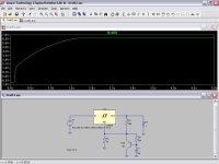
that circuit was found in the datasheet of National's LM150. it doesn't say anything about customizing the duration of the slow turn-on.
also can I also place a 10uF (after the 2nd 1N4002) from Vout to ground?
thanks for the help. 🙂
ps. I have just read a similar thread and there were a lot of off-topic replies. please do it somewhere else. 🙂
http://img112.imageshack.us/my.php?image=untitled3bf7.gif
that circuit was found in the datasheet of National's LM150. it doesn't say anything about customizing the duration of the slow turn-on.
also can I also place a 10uF (after the 2nd 1N4002) from Vout to ground?
thanks for the help. 🙂
ps. I have just read a similar thread and there were a lot of off-topic replies. please do it somewhere else. 🙂
it's for tube heaters.
2 questions:
1. increasing r3 also increases the delay?
2. how about c1?
thank you for the help
2 questions:
1. increasing r3 also increases the delay?
2. how about c1?
thank you for the help
Hi
R3 and C1 is tau or the time constant. The pnp is clamped on at turn-on so Vout is initially equal to Vref. The output slowly rises to the set output voltage after 3-4 time constants.
50K*100u= 5sec
so output goes from Vref to Vout in about 15-20sec
<edit>
This circuit is a good idea for heater warm up time and to prevent the Vreg from current limiting on start up.
I'd breadboard this up, and have a play with different values for R3 and C1. The maths is good to know, as Infinia points out, but the hands on approach is more fun, (for me, anyway).
can I use this: http://www.ortodoxism.ro/datasheets/toshiba/905.pdf
as the transistor in the circuit? just asking cause I already have it.
ps. to infinia: just sent you an email in regards to spice simulations. thanks again
as the transistor in the circuit? just asking cause I already have it.
ps. to infinia: just sent you an email in regards to spice simulations. thanks again
It would be simpler to avoid the transistor all together and use just a C across the lower divider resistor...The problem with that is the size of the C would be huge and expensive ...So the transistor and 10uF cap, 50K are acting as a Capacitive multiplier, looking in to the emmiter.... This way a smaller cap can be used..
Chris
Chris
- Status
- Not open for further replies.
- Home
- Amplifiers
- Power Supplies
- help customize "slow turn-on" duration in this circuit (link to schematics inside)