Hello, first-timer here so not sure if I’ve posted this is the right thread.
I have an audio interface — M-Audio Fast Track Ultra 8r — which has become obsolete in terms of manufacturer support and signal chain compatibility. The device does not have daisy chaining capacity, meaning I cannot integrate it into my signal chain as a digital device; hence, I wish to convert it to a standalone analogue preamp in order to plug it into an ADC to expand my I/O and integrate the device into my signal chain.
The idea is to somehow rewire (or de-wire) the internals to bypass the AD/DA converters between mic input to line output, making the signal flow completely analogue and unadulterated, to then be converted with an ADC.
This will likely be an audacious DIY job by myself — unless someone in the UK is willing to take on this task for me — as I have no electrical hands-on experience, so may botch things and lose a device. Thus, I need the DIY community’s help and guidance through the process.
This is the information I have gathered so far, though I am uncertain if it is entirely correct:
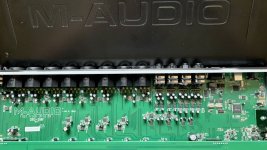
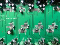
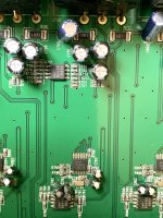
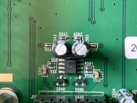
Receiving/Input amps: JRC4580 dual op amps
Gain op amps: THAT 1510
Individual TL072C JFET amp
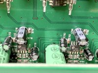
I do not know if there are buffer amps nor how to discern one. Kindly see the attached images and let me know if you can spot any.
Output op amps are also JRC4580
ADC are AK5386 rated up to 226/192kHz 24-Bit. There are 4, so I assume each one is for each stereo input pair.
DAC are AK4384 rated up to 192kHz 24-Bit. Also 4 of these.
Images of the PCB board are attached for anyone to offer guidance.
Any assistance and guidance would be greatly appreciated.
I have an audio interface — M-Audio Fast Track Ultra 8r — which has become obsolete in terms of manufacturer support and signal chain compatibility. The device does not have daisy chaining capacity, meaning I cannot integrate it into my signal chain as a digital device; hence, I wish to convert it to a standalone analogue preamp in order to plug it into an ADC to expand my I/O and integrate the device into my signal chain.
The idea is to somehow rewire (or de-wire) the internals to bypass the AD/DA converters between mic input to line output, making the signal flow completely analogue and unadulterated, to then be converted with an ADC.
This will likely be an audacious DIY job by myself — unless someone in the UK is willing to take on this task for me — as I have no electrical hands-on experience, so may botch things and lose a device. Thus, I need the DIY community’s help and guidance through the process.
This is the information I have gathered so far, though I am uncertain if it is entirely correct:
Receiving/Input amps: JRC4580 dual op amps
Gain op amps: THAT 1510
Individual TL072C JFET amp
I do not know if there are buffer amps nor how to discern one. Kindly see the attached images and let me know if you can spot any.
Output op amps are also JRC4580
ADC are AK5386 rated up to 226/192kHz 24-Bit. There are 4, so I assume each one is for each stereo input pair.
DAC are AK4384 rated up to 192kHz 24-Bit. Also 4 of these.
Images of the PCB board are attached for anyone to offer guidance.
Any assistance and guidance would be greatly appreciated.
Attachments

You really need a schematic for such a wide-ranging undertaking.
That is apart from the consideration if this is a recommended project.
It is a bit vague to me still what exactly you want to accomplish, but trying to mod an obsolent sound card is ambitious with no prior experience.
Jan
That is apart from the consideration if this is a recommended project.
It is a bit vague to me still what exactly you want to accomplish, but trying to mod an obsolent sound card is ambitious with no prior experience.
Jan

It looks like what you are wanting to do would just convert the Fast Track to a set of eight analogue mic preamps.
Would an analogue mixing desk not be a better bet rather than hacking this up?
Good luck with your project if you go ahead with it!
Cheers, and regards.
Ant
Would an analogue mixing desk not be a better bet rather than hacking this up?
Good luck with your project if you go ahead with it!
Cheers, and regards.
Ant
You have plenty of blank space in that product to put extra resistors & capacitors. OTOH there is a ground plane which is a pain to remove. Plus if it is a multilayer board, cutting the existing traces inside the board would be near impossible. JRC4580 is a very quiet op amp at high gains. Getting to the traces of those tiny surface mount parts would be difficult.
Gain is Rf/Ri where Rf is feedback resistor and Ri is input resistor, parallel from feedback pin to analog ground. In addition with fast op amps like 4580 it is usually necessary to bypass the feedback resistor with a small disk cap (22 to 47 pf) to kill the gain at above 100000 hz.
I would ditch the board, save the case & power supply and input/output connectors. I would build a 4580 circuit (or 2068 or 33078 or 5532 circuit) in DIP package that has more space between pins to land wires. I would build on perf board or NEMA CE board with ptp wires, avoiding the computer soltware requirements of circuit boards. Such software usually requires eterna/update Windows or Apple. Potentiometers would have to be mounted on a front panel to control volume, also possible low/high frequency boost or cut. If RIAA input, you will need resistors and capacitors in the feedback path to roll off the frequency curve. See analogue input forum for various examples.
Any switcher power supply for the A/D D/A (5 v) may cause interference with higher gain analog circuits. Even nearby transformers can cause hum.
Good luck and heppy diy hobby.
I couldn’t find a schematic per se, but I did find this link to someone who extracted the PCP board and has taken aerial images of its different planes.You really need a schematic for such a wide-ranging undertaking.
Does this help?
http://dhvan-assistenciatecnica.blogspot.com/2019/06/interface-de-audio-m-audio-fast-track.html?m=1
Greetings,
Ab
Last edited:
Hit the nail on the head, verbatim.It looks like what you are wanting to do would just convert the Fast Track to a set of eight analogue mic preamps.
Would an analogue mixing desk not be a better bet rather than hacking this up?
Unanimously; though, the device has sentimental value to me. It was my first 8 track 19” unit and I like the preamps. They’re clean, so I want to use it with an astronomically better dedicated external ADC for maximal signal quality. I would be using it for tom and cymbal spot mics, and it would fit into my 19” rack. If successfully modded, I don’t see myself needing different pres for this very specific usage, so it would likely remain on my rack for the indefinite future.
I don’t know of any completely analogue 8 channel preamps out there that are affordable (read: less than £200/$250); but in either case, I want to see if this mod is feasible as I would rather invest in better gear down the line than on a budget device that‘s preamps are inferior to the one I already have.
Greetings,
Ab
I’ve posted a link to Jan which shows the different planes of the device. I still don’t know enough to discern what I am looking at. What do you see?You have plenty of blank space in that product to put extra resistors & capacitors. OTOH there is a ground plane which is a pain to remove. Plus if it is a multilayer board, cutting the existing traces inside the board would be near impossible.
Thank you for this explanation! As a complete novice, I don’t know what all the minuscules diodes, resistors, and capacitors do and what functions they serve — as you mentioned about inhibiting hum above a certain frequency.JRC4580 is a very quiet op amp at high gains. Getting to the traces of those tiny surface mount parts would be difficult.
Gain is Rf/Ri where Rf is feedback resistor and Ri is input resistor, parallel from feedback pin to analog ground. In addition with fast op amps like 4580 it is usually necessary to bypass the feedback resistor with a small disk cap (22 to 47 pf) to kill the gain at above 100000 hz.
This is certainly the information rich suggestion. Thank you for that. Though, I cannot— in all transparency— say I understood any of it.I would ditch the board, save the case & power supply and input/output connectors. I would build a 4580 circuit (or 2068 or 33078 or 5532 circuit) in DIP package that has more space between pins to land wires. I would build on perf board or NEMA CE board with ptp wires, avoiding the computer soltware requirements of circuit boards. Such software usually requires eterna/update Windows or Apple. Potentiometers would have to be mounted on a front panel to control volume, also possible low/high frequency boost or cut. If RIAA input, you will need resistors and capacitors in the feedback path to roll off the frequency curve. See analogue input forum for various examples.
Any switcher power supply for the A/D D/A (5 v) may cause interference with higher gain analog circuits. Even nearby transformers can cause hum.
Will have to check the analogue form as you’ve suggested.
Is this all for a completely analogue preamp? Does all the apply for analogue* preamps only? There would be no AD/DA since I want to make the device an analogue preamp only.
Would this all then fit nicely back into the device?
Greetings,
Ab
diyaudio forum spells analog US way for analog line level forum, british way for analogue source forum. It is run from Britain I believe.Is this all for a completely analogue preamp? Does all the apply for analogue* preamps only? There would be no AD/DA since I want to make the device an analogue preamp only.
Would this all then fit nicely back into the device?
The circuits would fit in the case. I doubt there is a flat surface to mount 9 (volume) or 25 (plus tone controls) potentiometers. Probably the switcher power supply will drive the analog circuits nuts. Switcher supplies should be mounted in a separate grounded steel case, with inductor RF traps on all inputs and output. Else that, consumer products get away with distance and careful layout sometimes. You are not the engineer the guys at M-audio are, to use all the bag of tricks to kill RF howl in linear output.
My $15 Herald RA88a disco mixer had hiss (*****y 4558 op amps in a 50x gain circuit) and hum (transformer mounted too close to 50x gain circuits). I spent a year and $25 to pull the transformer out of the case, convert to external single voltage wall supply, change the op amps to 33078, change the ground scheme, and get rid of the oscillations that occured as a result of op amp upgrade. Very educational, and a superb sounding $40 RIAA preamp with additional inputs for CD & AM/FM radio.
Unanimously; though, the device has sentimental value to me. It was my first 8 track 19” unit and I like the preamps. They’re clean, so I want to use it with an astronomically better dedicated external ADC for maximal signal quality. I would be using it for tom and cymbal spot mics, and it would fit into my 19” rack. If successfully modded, I don’t see myself needing different pres for this very specific usage, so it would likely remain on my rack for the indefinite future.
I still use mine on an almost daily basis. Though not usually all eight ins / outs these days. Yeah, the preamps are all right, to be fair. It is still a reasonably good sounding unit, though a bit long in the tooth. The lack of Windows 10 drivers irks me a bit; means my DAW is stuck on Windows 7 for now, which is a bit of a pain. Just keep the DAW off the internet and it's OK, but sooner or later I'll need to deal with this. But not yet.....
I've not had the top off mine to see if conversion would be possible.I don’t know of any completely analogue 8 channel preamps out there that are affordable (read: less than £200/$250); but in either case, I want to see if this mod is feasible as I would rather invest in better gear down the line than on a budget device that‘s preamps are inferior to the one I already have.
I think others have hit the nail on the head: if it is a multi-layer PCB you'll likely struggle to achieve this. If it isn't then it might just be a case of cutting and linking PCB traces. But you'd really need a schematic to work out what is where; I've never seen a schematic for this in the wild.
The suggestion of replacing the electronics with some custom design would work too. But that's a whole new can of worms to open if you are a bit of a novice in this area......
Best of luck with it!
Cheers, and regards,
Ant
You need a circuit drawing, or you must be able to reverse engineer that circuit drawing, or you are smart enough to pinpoint the very spots to extract the desired signals and proces them to your liking. That's not a starter project, alas.
M-Audio is a reliable brand. Parts can be replaced if they become obsolete.
M-Audio is a reliable brand. Parts can be replaced if they become obsolete.
As ant moore pointed out, driver software is not being updated to keep up with windows updates. Without drivers that can be used, product is now obsolete. Landfill candidate, except for any analog parts that do not interface with software drivers.M-Audio is a reliable brand. Parts can be replaced if they become obsolete.
Hmm... the analogues everlasting, the digitals stumbling.
I'm a dinosaur, obsolete too... almost.
Thanks indianajo!
I'm a dinosaur, obsolete too... almost.
Thanks indianajo!
- Home
- Amplifiers
- Solid State
- Help: Converting Interface to Analogue Preamp