I'm still struggling to learn how to determine stability using LTSpice.
Attached is the same circuit but with connecting the TMC resistor on opposite sides of the AC source.
Can someone please help me out with how it should be done.
Thanks
Attached is the same circuit but with connecting the TMC resistor on opposite sides of the AC source.
Can someone please help me out with how it should be done.
Thanks
Attachments

I wish I knew.
Been working with LT over the past couple of weeks.
But not really making progress. Back to where I was when I reached Bob Cordell's instruction chapter.
Been working with LT over the past couple of weeks.
But not really making progress. Back to where I was when I reached Bob Cordell's instruction chapter.
Right there with you with confusion. I have been plotting the AC analysis of the two IPS input nodes. i.e. base of the LTP transistors. This is the Bode plot. I think. Plot the output and see where gain drops to zero. By theory, you need to have less than 45 degrees or so at all times with gain to be rock solid in worst case. Clipping will excite about everything and 2 Ohms is insane. I think. I have worked this out by myself and can't get much in the way of help.
Measure out to 200Meg or more.
I then excite the amp with a signal about 10% over clipping and decrease the load to about 2 Ohms.
I can't get what I see in the Bode plot to always correlate. Some clever math function in LTSpice should actually be able to subtract the two phases and give you a single difference plot, but I have not made that work.
Here is what I mean. The plot looks great, but it failed in the transient sim as I described.
Attachments
Made a little progress in tuning the FFT parameters. Looking at the noise test.
OK, I get a nice plot and a box that is helpful in telling me my amp has a noise density of 112nV Hz 1/2. I have an output of 22VRMS. I have a gain of 27. How do I get from the noise figure to something I can use to solve 20*log Sig/noise ? Cordell says "this can be very helpful" Well, not helpful enough.
What is helpful is to bounce around and see which components contribute how much.
HI all
Not had any luck with commercial simulators. Wrote my own and you can then solve for voltage phase-gain and current phase gain and combine the two to give the overall stability margin. (R D Middlebrook, Measurement of loop Gain in Feedback Systems), Int. J. Electronics, 1975, vol 38, no4, pp485-512).
However, AC analysis IMHO does not simulate the full possible conditions in an amplifier using Class AB output stages. The frequency response of a transistor depends on the current so phase shifts can be changing with current, and A.C. simulations generally, therefore, work only using the quiescent bias conditions in the amp - not the conditions when a power device is pushing out amps!
I have found transient simulations easier and more realistic.
John
My problem is I don't know which side of the voltage source to connect the TMC resistor.
Previously I had the TMC resistor connected on the feedback resistor side.
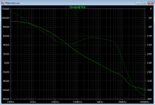
And although this showed a acceptable phase margin at the point where the gain reached zero.
The sim showed that the phase dropped to less than 20deg around the 10kHz area.
For stability I would assume that we require more than 45deg over the complete frequency range until the gain reaches zero.
But I'm following Ostrippers thread on VFA/CFA builds.
On his thread I saw that he places the TMC resistor on the Output side.
When I simmed my amplifier with the same connection the sim showed no dramatic decrease in phase at the 10kHz area and sloped like normal reaching 0dB gain with acceptable phase margin all the way.
I was hoping that some of the LTSpice gurus would share some of their knowledge.
Regards
Previously I had the TMC resistor connected on the feedback resistor side.
And although this showed a acceptable phase margin at the point where the gain reached zero.
The sim showed that the phase dropped to less than 20deg around the 10kHz area.
For stability I would assume that we require more than 45deg over the complete frequency range until the gain reaches zero.
But I'm following Ostrippers thread on VFA/CFA builds.
On his thread I saw that he places the TMC resistor on the Output side.
When I simmed my amplifier with the same connection the sim showed no dramatic decrease in phase at the 10kHz area and sloped like normal reaching 0dB gain with acceptable phase margin all the way.
I was hoping that some of the LTSpice gurus would share some of their knowledge.
Regards
My problem is I don't know which side ...to connect the TMC resistor...
I have a whole article on stability probe technique ready for Linear Audio with a lot of explanation.
The short summary is that neither is correct for this circuit.
It is better to think of this as "where to place the probe".
Placement in the outer loop, your second plot, is quite deceptive and can lead to a false sense of stability.
Before the VAS transistor provides a much more accurate estimate of stability in this circuit.
You should use a proper Tian probe because the V source method is OK after the OPS but is not reliable to use in other locations.
Tian probe is in the LTspice libraries, with instructions.
Once you have the .AC stability correct then you should definitely follow John's advice and do .TRAN as well.
They provide different information and are both useful.
Best wishes
David
Last edited:
Thanks for helping Dave,
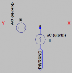
If I use the Tian Probe, could you please help me place it in this circuit
I labeled the who ends of the probe. I'm not sure exactly where to break the circuit to insert the probe properly.
Thanks again for your time
If I use the Tian Probe, could you please help me place it in this circuit
I labeled the who ends of the probe. I'm not sure exactly where to break the circuit to insert the probe properly.
Thanks again for your time
Attachments

...
If I use the Tian Probe, could you please help me place it in this circuit
Directly in the lead to the base of Q4 and post your result so I can check.
Best wishes
David
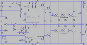
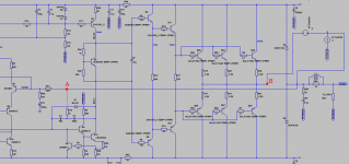
I think this is the conventional way to connect the Tian probe.
But I have the same question about the resistor.
Is it in the correct place in position A, or in position B.
Or maybe placed somewhere completely different
Regards
EDIT: sorry posted to fast, Ill place it as you advice
But I have the same question about the resistor.
Is it in the correct place in position A, or in position B.
Or maybe placed somewhere completely different
Regards
EDIT: sorry posted to fast, Ill place it as you advice
Attachments
I think this is the conventional way to connect the Tian probe.
The conventional position is actually incorrect.
But for simple Miller compensation it is usually does work.
Once you have TMC then the position that looks conventional is NOT useful.
There was much confusion in the early discussion of TMC due to failure to understand this.
The position with the Tian probe before the resistor is much closer to accurate.
That is "A" in you ASC.
Best wishes
David
Late here. More tomorrow.
Last edited:
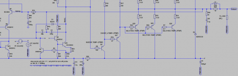
🙂 Ok here's my next try.
Attached is the .asc and all models if that makes it easier.
That looks correct. You run it and post the plot.
If there is a problem then I can download and check your .ASC and models.
Best wishes
David

HI all
Not had any luck with commercial simulators. Wrote my own and you can then solve for voltage phase-gain and current phase gain and combine the two to give the overall stability margin. (R D Middlebrook, Measurement of loop Gain in Feedback Systems), Int. J. Electronics, 1975, vol 38, no4, pp485-512).
However, AC analysis IMHO does not simulate the full possible conditions in an amplifier using Class AB output stages. The frequency response of a transistor depends on the current so phase shifts can be changing with current, and A.C. simulations generally, therefore, work only using the quiescent bias conditions in the amp - not the conditions when a power device is pushing out amps!
I have found transient simulations easier and more realistic.
John
John,
It is the discrepancy between the AC analysis Bode plot and the performance of the Transient analysis where I was having issues. Your reasoning makes sense, but it leaves us stabbing in the dark. I am going to look at the AC parameters to see if they can be modified to provide the same Bode plot right below clipping and right above.
I have a whole article on stability probe technique ready for Linear Audio with a lot of explanation.
The short summary is that neither is correct for this circuit...
Dave,
Darn, I guess I'll have to send two paychecks to Jan ( Is his payment currency converter working again? I could not buy the issues I wanted the other day). Anyway, I don't understand two things here:
Why is an AC source being added to the feedback line? Why can't the amp input be feed, a representative difficult load be added, and just look across the input diff pair? Is that not the simulation point that is important? Input to feedback? Is the TMC doing something else I don't understand?
Second, never heard of the Tian probe. Got to go looking for that.
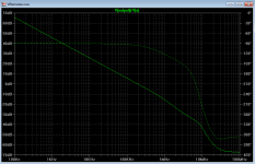
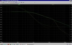
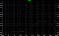
Attached are the output plot as is.
And with the formula in the second plot.
It is not clear what you have probed in the first plot.
But the Tian probe in second plot looks believable and is stable.
Best wishes
David.
...send two paychecks to Jan.
I'll try very hard to make sure I have the article finished on time😉
In the meantime the introductory article is already published in Vol. 6.
I can't be very objective about my contribution but the other articles are worth the price anyway.
Anyway, I don't understand two things here:...
Second, never heard of the Tian probe.
Lots of stuff on the Net about feedback theory.
The Tian article itself is on-line
Best wishes
David.
Thanks, I found:
Plotting Loop Gain Using the Tian Method - Spring 2011
That should keep me off the street a while.
I really want the articles about bias servo and some new ideas on output topology. One needs to think of L-A is not a magazine, but a periodic book series. The price is easier to swallow that way. The two I have have been well worth the price!
http://www.kenkundert.com/docs/cd2001-01.pdf
https://sites.google.com/site/frankwiedmann/loopgain
While I spend the day digesting this (good thing Monday is a Holiday), is there a way to do the same Bode plot I described, but at a higher current?
https://sites.google.com/site/frankwiedmann/loopgain
While I spend the day digesting this (good thing Monday is a Holiday), is there a way to do the same Bode plot I described, but at a higher current?
- Status
- Not open for further replies.
- Home
- Amplifiers
- Solid State
- Help connection for Phase Measurement