Let's start with Joppa's Rule\
A rule which i have found is not very useful.
dave
...my very own first project based on Phi by Klang und Ton design…
Now i want some sweet single ended class A amp, and choice is boiling down to couple second hand projects and one solid state.
I see an XO, what does the speaker's measured impedance look like. With an SE amp, the typically high Rout means the amplifier will interact with the speaker impedance.
95dB means nothing if the impedance is not flattish.
dave
The builder of your amplifier really took inspiration from the past, at least on safety matters. Speakers wires were sometimes left floating on tube radios; disconnecting them from the ground was also a dirty trick of cheap servicemans, to avoid replacing faulty transformers while still being paid for a "repair". If your output transformers are of the old style kind, there is little insulation between primary and laminations and primary winding to secundary. The positive supply may leak to speaker terminals or laminations. I once got a electrical shock while touching the speaker terminals due to missing ground connection and a faulty transformer. To be on the safe side, do not touch the metal parts of speaker binding posts (both at the amplifier and at the speaker side) or the transformer laminations while the amplifier is turned on.
Old consumer grade reclaimed potentiometers often have poor tracking between left and right section and attenuation curves was a bit random; replacement is a good idea. Unfortunately, your mid-bass distortion at increased level may simply be the audible consequence of output transformer limitations paired with the lack of global feedback and the obvious low effort at the point to point wiring. Start by replacing the potentiometer, then check the situation.
Old consumer grade reclaimed potentiometers often have poor tracking between left and right section and attenuation curves was a bit random; replacement is a good idea. Unfortunately, your mid-bass distortion at increased level may simply be the audible consequence of output transformer limitations paired with the lack of global feedback and the obvious low effort at the point to point wiring. Start by replacing the potentiometer, then check the situation.
I see an XO, what does the speaker's measured impedance look like. With an SE amp, the typically high Rout means the amplifier will interact with the speaker impedance.
95dB means nothing if the impedance is not flattish.
dave
This is the graph from builder's guide.

Regarding volume potentiometer, since i really dont know, what should i be looking for as replacement, any particular type or so ? Rather not to spend some crazy money either, just a regular volume pot.
Alps RK27 , 50K , should do the job nicely. The original from RS Components or other distributors is comparatively expensive but the parts from China, although probably fake, are still good enough.
Alps RK27 , 50K , should do the job nicely. The original from RS Components or other distributors is comparatively expensive but the parts from China, although probably fake, are still good enough.
I found one guy selling locally, price is 15e.

.png")
But he doesnt have 50k, only
10K, 20K, 100K i 500K
Will 20K do ?
Also, the more i think, how hard would be to rebuild/rewire entire amp ? Is it possible to add more power to it by adding more tubes ? I can buy 6p6's for 20e pair and have additional ECC82 tube for preamp as spare.
Last edited:
On my builds I use 10K when the source is solid state, 100K when the source is a tube preamplifier, and 50K as a reasonable compromise that works on both. A lower value does load the source more, but it may decrease unwanted background noise.
Mainstream tube amplifiers are constrained by the power envelope of the output and power transformers. Your output transformers have been recovered from a vintage record player. The overhelming majority of that kind of transformers is built to bring the output tube at the optimal power when speaker impedence is between 3 or 4 ohm; your speaker impedence is higher so your available power is less than the original design value, and it rarely was more than 3W per channel. You have good speakers, so my guess is that your amplifier can deliver less than 2W before distortion becomes noticeable. On my experience this power level is typical of this type of low skill budget designs. Often something can be done to improve the performance. If you want a more useful help from forum members, you should provide pictures of the inside, schematic diagram, and at least the actual value of the high voltage power supply and the voltage at the power tube cathode. Be careful when taking measurements. On this kind of builds with unsecured wires, I usually use hook probes to keep fingers away from any metal parts or wires.
Mainstream tube amplifiers are constrained by the power envelope of the output and power transformers. Your output transformers have been recovered from a vintage record player. The overhelming majority of that kind of transformers is built to bring the output tube at the optimal power when speaker impedence is between 3 or 4 ohm; your speaker impedence is higher so your available power is less than the original design value, and it rarely was more than 3W per channel. You have good speakers, so my guess is that your amplifier can deliver less than 2W before distortion becomes noticeable. On my experience this power level is typical of this type of low skill budget designs. Often something can be done to improve the performance. If you want a more useful help from forum members, you should provide pictures of the inside, schematic diagram, and at least the actual value of the high voltage power supply and the voltage at the power tube cathode. Be careful when taking measurements. On this kind of builds with unsecured wires, I usually use hook probes to keep fingers away from any metal parts or wires.


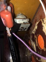


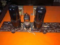
As you may guess, a build that includes hot glue in the bill of materials does have room for improvements. Start by replacing the vintage volume pot and check if the background noise will reduce to acceptable levels. The next easy step will be to reconfigure the output tube as triode. I see wires with a "G2" label attached to them, it may be something already tried by the original builder. Then it could be possible to try adding global feedback to reduce distortion, this would probably require the replacement of the ECC82 tube and reworks to the wiring. I would then seriously consider the idea of a full rebuild on a proper chassis, because this one is a horror story, security wise. The purple wire,detached from the chassis, from the safety ground pin of the IEC connector to the main signal ground solder blob, is quite unique.
Alright,
I will buy the pot, if he has 50k, if not i will buy 20k. For my upcoming project should i buy 100k pot aswell ? It will be tube aswell.
Next week i will try to replace the pot, doesn't seem that difficult to do.
My speaker cabinets are few weeks away from being finished. I wanted to put together crossover and connect speaker as is just to play with them a bit, but now that output terminal is not grounded, maybe best to wait 🙂 Or try different amp i have laying around.
Ok, i bought 20k pot.
Now the bad news.
Old pot is, get this, 470k lol, and you were right about hot glue of death, as it took its first victim, 0.25uF(0.27uF) 630v cap that goes to tube. While trying to remove hot glue with scalpel, cap was back to back with plastic front cover, and i scalped it, its gone now.
So, all things considered, should i add resistor to the pot to increase its resistance ? also what cap should i replace the damaged one ? Same as old one ? What is important here, capacitance or voltage ?
Thanks.
Last edited:
470k is a fairly common value on tube radios and vintage record players, but the source was a high impedance piezo cartridge or tube tuner. 20K is a better value for a Hi-fi amplifier due to the low output impedance of modern sources. A lower impedance minimizes hum and stray HF noise. The capacitance value need to be adapted to the potentiometer; the capacitor and the potentiometer are a RC high pass filter. Check a online filter calculator. A good walue for 20K potentiometer is in the 1 to 4 uF range. It is possible to use 63V film capacitors as amplifier input. I often use 400V or 630V parts because they cost almost the same and can be used as coupling capacitors, that way I don't need to stock a different part. Next time you try to remove hot glue, I suggest to soften it with a hot air gun; use paper or masking tape to deflect hot air away from sensitive parts.
I have a pair of 1uF MPX-X2 250v caps, will they do ?
https://www.es.co.th/Schemetic/PDF/MPX_MKP.PDF
Also what wire should i use to solder it, since leads are very short.
https://www.es.co.th/Schemetic/PDF/MPX_MKP.PDF
Also what wire should i use to solder it, since leads are very short.
Hi, as Pcan wrote, It doesn't have, the circuitry, to be bonded and attached firmly necessarily. That Is a thing seen in car audio, where vibrations occur by the vehicle moving....
You May take advantage of 3 dimensional montage.
This applies well also to crossover...montage!
You May take advantage of 3 dimensional montage.
This applies well also to crossover...montage!
😕 Class X-2 is for other uses, i.e. self extinguant in case of explosion for current surge at switch-on of Power buttons
So, i replaced the pot and installed caps. I must say, all the background noise and hissing went away. There is still some distortion after 3/4 volume, but amp was quite bit cold, maybe 1-2min of working. Its quite late so i couldnt test at loud volumes.
I will take some pics tomorrow.
Thanks pcan for pot recommendation, its like amp has been rebirthed.
I will take some pics tomorrow.
Thanks pcan for pot recommendation, its like amp has been rebirthed.
Last edited:
- Home
- Amplifiers
- Tubes / Valves
- Help chosing second hand tube amp for 95db speakers