Hello there!
I have two goals:
Other than any feedback you have I am wondering:
This is the circuit I get and the simulation with a 8-ohm load. I didn't set the ESR of the capacitors. I cannot measure it right now.


I have two goals:
- Get a capacitance multiplier for a chip amp (TDA7377 / STA540)
- Learn how to make a PCB with Kicad
Other than any feedback you have I am wondering:
- Maybe more than one output transistor is overkill but I'd like to keep at least two to have them run cool. Is it OK?
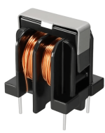
- I have a small dual-40mh coil. Is it useful to make a low-pass before the BD139 base with it? BTW, I joined pins to make a single coil and measured 120mH. Wondering if that's useful.
This is the circuit I get and the simulation with a 8-ohm load. I didn't set the ESR of the capacitors. I cannot measure it right now.
Attachments
Last edited:
Also needs a protection diode between the output (anode) and the BD139 base (cathode).
Thanks! Added. Also spitted the first capacitor and they're 2 x 4700uF now.

Hello,
Are you sure this kind of choke can be used? Looks more like one used for AC ( no airgap).
So called common mode choke. If you connect it differently it will probably run really hot
But wait for the real experts.
Greetings Eduard
Are you sure this kind of choke can be used? Looks more like one used for AC ( no airgap).
So called common mode choke. If you connect it differently it will probably run really hot
But wait for the real experts.
Greetings Eduard
Hi Eduard.
Not sure 🙂 I am not using it now, unless I get confirmation it's a good idea and that it doesn't introduce oscillations.
The idea is to use it in a low pass. The current I get through it in the simulation is 150mA. I added to the diagram below. Symbols crossed in red are for the simulation and not for the PCB.


Are you sure this kind of choke can be used? Looks more like one used for AC ( no airgap).
Not sure 🙂 I am not using it now, unless I get confirmation it's a good idea and that it doesn't introduce oscillations.
The idea is to use it in a low pass. The current I get through it in the simulation is 150mA. I added to the diagram below. Symbols crossed in red are for the simulation and not for the PCB.


- Home
- Amplifiers
- Power Supplies
- Help check RCRCRC and cap mult