Can you please help me figure out what's the cutoff frequency of this filter? Should resistor R209 be included in the calculation? If yes then how?

Thank you,
Rado
Thank you,
Rado
So its a low pass filter. The standard design method doesn't seem to have been used here as C207 should be twice the value of C208, and R210 and R211 should be equal.
Normally you need to know the value you want the response to be -3db down and then begin by picking a suitable (ball park figure) for cap C208. Make C207 twice the size and calculate the resistors from the formula:
Calculate R210 and R211:
= 1/(2 * 1.414 *pi *C208*Frequency)
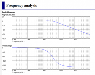
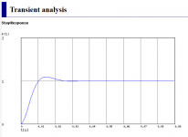
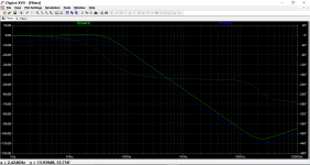
Having just thrown those values into a standard LPF simulation we can see the response is -3db down at around 48Hz.
Putting 48 Hz into the formula gives 23500 ohms for each resistor. That is for the standard LPF version where the resistors are equal.
R209 has no effect because it is always assumed that the filter is fed from a low impedance source (such as another opamp output).
Normally you need to know the value you want the response to be -3db down and then begin by picking a suitable (ball park figure) for cap C208. Make C207 twice the size and calculate the resistors from the formula:
Calculate R210 and R211:
= 1/(2 * 1.414 *pi *C208*Frequency)
Having just thrown those values into a standard LPF simulation we can see the response is -3db down at around 48Hz.
Putting 48 Hz into the formula gives 23500 ohms for each resistor. That is for the standard LPF version where the resistors are equal.
R209 has no effect because it is always assumed that the filter is fed from a low impedance source (such as another opamp output).
Attachments
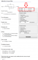
It is a Sallen and Key second order low pass filter. Lots of info on the web. You can independently choose corner frequency and Q.
horrible !
and if that were connected to a speaker that also had a bump in it's frequency response of higher Q it would boom objectionably.
But equally it could be to a driver that had a low Q roll off and the filter compensates for that.
and if that were connected to a speaker that also had a bump in it's frequency response of higher Q it would boom objectionably.
But equally it could be to a driver that had a low Q roll off and the filter compensates for that.
First, thank you all for answers.
The circuit is supposed to be from original Klipsch Promedia 2.1 speaker. I'm adding full schematic of subwoofer preamp path. It's from this website: Klipsch Promedia V2.1 Amplifier Repair
Based on your responses online calculators suggest following cutoff frequencies:
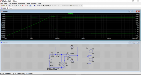
High pass filter fc = 56.3 Hz (from first image)
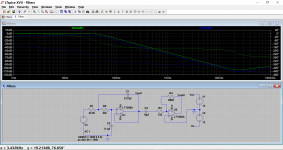
Low pass filter fc = 42.6 Hz (from second image)
The reason why I was asking is that based on subwoofer frequency response from specs I expected to see a band pass characteristic of combined filters between 30Hz and 100Hz for the subwoofer. Range from 56Hz to 42Hz makes no sense. Am I missing something, or is schematic possibly wrong?
Highpass section:

Lowpass section:

And real reason for asking is that my amp is blown and I'd like to build a new one and properly filter low freuency for the subwoofer.
Thanks,
Rado
The circuit is supposed to be from original Klipsch Promedia 2.1 speaker. I'm adding full schematic of subwoofer preamp path. It's from this website: Klipsch Promedia V2.1 Amplifier Repair
Based on your responses online calculators suggest following cutoff frequencies:
High pass filter fc = 56.3 Hz (from first image)
Low pass filter fc = 42.6 Hz (from second image)
The reason why I was asking is that based on subwoofer frequency response from specs I expected to see a band pass characteristic of combined filters between 30Hz and 100Hz for the subwoofer. Range from 56Hz to 42Hz makes no sense. Am I missing something, or is schematic possibly wrong?
Highpass section:
Lowpass section:
And real reason for asking is that my amp is blown and I'd like to build a new one and properly filter low freuency for the subwoofer.
Thanks,
Rado
Last edited:
The HPF has the following response. There is an overall gain of around 3db in the passband.
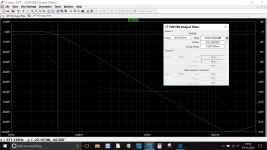
The additional AC coupled inverting stage on the LPF modifies the response as shown here. You can see the two output voltages marked on the diagram, Vout1 and Vout2. The -3db point as simulated was around 40 Hz.
The additional AC coupled inverting stage on the LPF modifies the response as shown here. You can see the two output voltages marked on the diagram, Vout1 and Vout2. The -3db point as simulated was around 40 Hz.
Attachments
- Status
- Not open for further replies.
- Home
- Source & Line
- Analog Line Level
- Help calculating low pass filter frequency