Hello hello everyone,
I am French, I do not speak English and I translate with Google translation and I apologize
help blog amplifier VTL 35 Triode.
After long years of service one of my 35 blocks dropped me HS output transformer.
I can not find the diagram of this VTL 35 Triode, I sent an email to VTL Amplifiers, Inc | Handmade In USA to ask them to help me
a photocopy of a diagram or the characteristics of the output transformer (input impedance)
they kindly replied that it was better to buy a new amplifier, commercially I find it very average ...
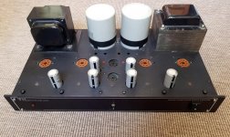
my VTL 35 Triode blocks. These are double push-pull, the tubes of 4. 5888 and 2. 6201 on each block.
Can you help me with information or advice?
I thank you in advance.
cordially
I am French, I do not speak English and I translate with Google translation and I apologize
help blog amplifier VTL 35 Triode.
After long years of service one of my 35 blocks dropped me HS output transformer.
I can not find the diagram of this VTL 35 Triode, I sent an email to VTL Amplifiers, Inc | Handmade In USA to ask them to help me
a photocopy of a diagram or the characteristics of the output transformer (input impedance)
they kindly replied that it was better to buy a new amplifier, commercially I find it very average ...
my VTL 35 Triode blocks. These are double push-pull, the tubes of 4. 5888 and 2. 6201 on each block.
Can you help me with information or advice?
I thank you in advance.
cordially
What is it you want to do? Replace the output transformers? Perhaps VTL will sell you a new transformer. Otherwise replace both OPTs with ones made closer to where you live. If you use anything other than VTL transformers the resale value will be much lower.
Steve
Steve
Hello Steve,
VTL advises me to change the amplifier. I am trying to find VTL output transformer is very difficult, if not impossible.
This is why I want to find the characteristics of the original one to find the closest one.
And I am also looking for the VTL 35 triode diagram so that my suitable repairer is close to the origin if you have any ideas?
Or relationships at VTL, I want help!
Thanks Steve
I have three solutions.
The first: throwing the two VTL blocks in the trash.
The second: find a second-hand transformer for this model. (Not easy to find in France)
The third: find a replacement transformer.
Any advice will be helpful.
Thank you all
The first: throwing the two VTL blocks in the trash.
The second: find a second-hand transformer for this model. (Not easy to find in France)
The third: find a replacement transformer.
Any advice will be helpful.
Thank you all
Don't throw them in the trash, if you think you are going to do that, send them to me! 🙂 🙂 🙂
I think you need to find a replacement output transformer. Hopefully you can also get a print of the schematic. You may want to ask Manley Labs, they sold a version of this amplifier - Manley 35 and 50 Watt Monoblocks and Tiny Triodes — Manley Laboratories, Inc.
I think you need to find a replacement output transformer. Hopefully you can also get a print of the schematic. You may want to ask Manley Labs, they sold a version of this amplifier - Manley 35 and 50 Watt Monoblocks and Tiny Triodes — Manley Laboratories, Inc.
The third: find a replacement transformer.
I would find "two" replacement. Start with the defective channel, if you like the result buy one for the 2nd channel so both channels sound the same.
I would try a 4-6K primary output transformer good for 40-50W. Better yet, if you know how to work with HIGH Voltage, just check the AC voltage using a DVTM at the speaker secondary and between the two anode of the output tubes. Divide the primary voltage to the secondary voltage. Call that N. The secondary (a-a) impedance = N square x R secondary. Let say N = 24 and the speaker load is 8 ohms. Z= 24x24x8 = 4.5K. You can play a 1KHz signal via you tube if you don't have a signal generator.
to Roul
Consider a re-wound of trafo
Try to contact F.I.A.T. in Rome they are doing a good job.They are farfrom you but it is a good solution
They have a beatiful machine to make audio trafos.
fiat-trasformatori@libero.it
Consider a re-wound of trafo
Try to contact F.I.A.T. in Rome they are doing a good job.They are farfrom you but it is a good solution
They have a beatiful machine to make audio trafos.
fiat-trasformatori@libero.it
Hello everyone and thank you!
When I dismantled my output transformer I noticed that there was a name written inside FENDER.
FENDER output transformers have an impedance of 2k2.
I deduce that these are not the original transformers! (I may have been rolled when I bought the used amps)
but it works pretty well anyway! But I think it could work better with better adapted transformers
this is why I really need the diagram, or the input impedance of the original output transformer.
To be able to have transformers manufactured. I'm also looking for photographs of the original model,
and all the information the VTL Triode 35 mono blocks
1000 thank you all !!!! And again sorry for my English Google translation
Can you post some photographs of what you're looking at?
Depending on how old they are, that could be the correct transformer.
Depending on how old they are, that could be the correct transformer.
What is the big deal about the diagram? It will take an hour or so to draw it from looking at the amp. And for what purpose? It is going to be pretty standard.
If you need the transformer characteristics in order to find a good replacement you don't need a diagram anyway, just measure the working unit.
You will get more sensible advice if you upload a few pics.
Btw, you can probably get some good money out of selling the set on Ebay. Is it not the easiest way out?
Can you post some photographs of what you're looking at?
Attachments
Last edited by a moderator:
The links you could view the images of my VTL 35 Triode amplifier.
2020-03-24-16-32-00 — ImgBB
2020-03-01-16-08-27 — ImgBB
2020-03-24-10-17-38 — ImgBB
2020-03-24-10-18-36 — ImgBB
2020-03-24-16-32-00 — ImgBB
2020-03-01-16-08-27 — ImgBB
2020-03-24-10-17-38 — ImgBB
2020-03-24-10-18-36 — ImgBB
Hello everyone from Paris
I'm still looking for information on the VTL 35 Triode amplifier blocks.
Everything interests photos, diagrams, and of course advice on replacing my output transformers.
Thanks again
Claude
I'm still looking for information on the VTL 35 Triode amplifier blocks.
Everything interests photos, diagrams, and of course advice on replacing my output transformers.
Thanks again
Claude
- Home
- Amplifiers
- Tubes / Valves
- help blog amplifier VTL 35 Triode.