Goodmorning everyone.
I apologize in advance for the incorrect use of the English language, as I help myself with my knowledge and the use of the translator.
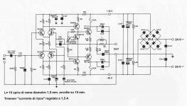
I need help setting up a self-built class A amplifier. The scheme was taken from a magazine from the 70's and it seemed valid to me. The problem is that I am not sure how to measure the quiescent current which is 1.5 A. There are two transistors per branch (BDW83 - BDW84) and the power supply is +30/32V e -30/32V. The emitter resistances are 0,22 Ohm. I don't have an oscilloscope but only an analog and another digital meter.
After shorting the input and without load, can you tell me step by step where to place the tester and what values should I read?
I hope in the meantime to find out how to post diagram and photos to also have an opinion on the circuit and any possible improvements.
Thank you
Carlo
You should read 0.33V between the legs of one of the two 0.22ohm resistor.
V=RI (Ohm's law)
0.33V = 0.22ohm x 1.5A
Saluti,
Jacques
V=RI (Ohm's law)
0.33V = 0.22ohm x 1.5A
Saluti,
Jacques
Last edited:
I hope in the meantime to find out how to post diagram and photos to also have an opinion on the circuit and any possible improvements.

Like this 🙂
How to attach images to your posts.
You should read 0.33V between the legs of one of the two 0.22ohm resistor.
V=RI (Ohm's law)
0.33V = 0.22ohm x 1.5A
Saluti,
Jacques
Thank you. Yes, this was clear to me but a confirmation is always useful. What I really wanted to clarify is where it is more correct to read the bias current directly: on the power supply branch that powers the board or on the one that goes to each collector of the transistors?
Sorry
Thank you. Yes, this was clear to me but a confirmation is always useful. What I really wanted to clarify is where it is more correct to read the bias current directly: on the power supply branch that powers the board or on the one that goes to each collector of the transistors?
Thank you. Yes, this was clear to me but a confirmation is always useful. What I really wanted to clarify is where it is more correct to read the bias current directly: on the power supply branch that powers the board or on the one that goes to each collector of the transistors?
The current measured directly from the power supply will include the bias current for the output transistors and the current for the other stages of the amp (a few additional milliamps). In the case of class A amp the latter is negligible. Some amps avec fuse holders on each rail allowing to measure current with the fuse removed.
Measuring current on the output transistor collector requires unmounting/de-soldering and is not practical.
Measuring voltages as I suggested is the easiest/more precise. But it is a good exercise to try the other methods.
Measuring current on the output transistor collector requires unmounting/de-soldering and is not practical.
Measuring voltages as I suggested is the easiest/more precise. But it is a good exercise to try the other methods.
I am not an expert in amp design but many others here are.
The rail voltage is very high for this kind of outputs in class A.
Make sure to use a lot of heatsink and/or active cooling.
It will increase your power bill significantly and will generate lots of heat.
Not recommended for the Italian summer unless your listening room is air conditioned 😀.
The rail voltage is very high for this kind of outputs in class A.
Make sure to use a lot of heatsink and/or active cooling.
It will increase your power bill significantly and will generate lots of heat.
Not recommended for the Italian summer unless your listening room is air conditioned 😀.
Actually, I have already made these measurements but they did not remain constant and this made me think that I was doing something wrong or that a different procedure should be used for a class A amplifier.
I have no engineering studies but only a diploma in telecommunications which, although it helped me a lot, does not allow me to design the devices of my passion.
I tightened the transistors on the heatsinks more, thinking of a non-optimal contact.
I have no engineering studies but only a diploma in telecommunications which, although it helped me a lot, does not allow me to design the devices of my passion.
I tightened the transistors on the heatsinks more, thinking of a non-optimal contact.
It is normal for the current bias to vary especially when the amp is warming up.
You should monitor it until the amp has reached its equilibrium temperature, like for an hour or so. Check the outputs temperature as well as it should not exceed 50-55°C (ideally < 25°C above room temperature).
You should monitor it until the amp has reached its equilibrium temperature, like for an hour or so. Check the outputs temperature as well as it should not exceed 50-55°C (ideally < 25°C above room temperature).
I am not an expert in amp design but many others here are.
The rail voltage is very high for this kind of outputs in class A.
Make sure to use a lot of heatsink and/or active cooling.
It will increase your power bill significantly and will generate lots of heat.
Not recommended for the Italian summer unless your listening room is air conditioned 😀.
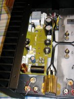
The amplifier has performed excellently for a long time previously thanks to optimization by an engineer friend and the appropriate instrumentation. Unfortunately I had the unfortunate idea to review the pcbs and the whole arrangement. but I could no longer have the help of that friend.
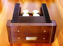
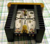
The amp should deliver around 30W and even if it seems a lot for a pair of transistors with that case, but it never gave any problems, before the change, also thanks to an all-aluminum cabinet that forms a single body with the heatsinks, helping them .
The 30W output power is not a problem for these darlingtons in class AB designs. Due to the poor efficiency of class A amps, they will have to dissipate here a total power probably in excess of 100W/channel. Mostly in heat and constantly.
The whole block, made up of interconnected aluminum pieces and all with dissipating function, excluding transformers, large capacitors and the wooden front, has a weight of about 12 kg.
Absolutely nothing. I just wanted to perform an upgrade and I ran into some problems during the setup.
However, I expect someone to examine the pattern and express their impressions.
However, I expect someone to examine the pattern and express their impressions.
- Home
- Amplifiers
- Solid State
- help bias setting


