I am trying to build a choke input filter similar with the schematic below. The LL1651 has 500Vrms output, after rectifier it's about 700v peak. however the LL1638 has the following limitation:
Max. ripple voltage at rec. DC current 300v rms.
with this limitation, will 700v damage the choke? I am not going to pull all of the 200ma DC from the choke but still worried. where I missed?

Max. ripple voltage at rec. DC current 300v rms.
with this limitation, will 700v damage the choke? I am not going to pull all of the 200ma DC from the choke but still worried. where I missed?
Last edited:
In my experience making choke input filter, it is extremely difficult to damage such a choke kind, it is only a piece of (long) copper wire. More easily you can damaged the rectifier or the SS diodes.
As those chokes have large air gaps in order to not saturate the core with the DC current and AC voltages across the coil, it is difficult to saturate the core. And if it happens, the choke disappears from the circuit and then you get cap input filter with its own pros and cons.
As those chokes have large air gaps in order to not saturate the core with the DC current and AC voltages across the coil, it is difficult to saturate the core. And if it happens, the choke disappears from the circuit and then you get cap input filter with its own pros and cons.
Wouldn't the first choke see around 500 volts rms (or a bit less) at its input and around 400 volts or so DC at the output of the first choke. If we say the rms value of DC is just the DC value then you have 100 volts rms across the choke. Well within spec.
Does it work like that?
Does it work like that?
Thanks
found the following: "The voltage rating must be higher than the supply voltage, or the insulation on the wire may break down, shorting the supply to the frame".
but I am not sure the 300Vrms in LL1638 is talking about the supplied voltage from the rectifier? or the voltage swing within the choke itself. if it's later one, I am safe...
Wouldn't the first choke see around 500 volts rms (or a bit less) at its input and around 400 volts or so DC at the output of the first choke. If we say the rms value of DC is just the DC value then you have 100 volts rms across the choke. Well within spec.
Does it work like that?
I hope, and most likely, that's the interpretation of "Max. ripple voltage at rec. DC current " meaning the voltage swing in the choke not the supplied voltage. but then what will be the max voltage I can supply to the choke?
If anyone can confirm, that will be appreciated.
I suggest you use PSUD2 to calculate the rms voltage across choke, and appreciate how your power supply is likely to perform.
It is likely the first choke will experience about 200-220Vrms across it, but there is likely to be start-up transients that could exceed 300Vrms for a few mains AC cycles. Best you check with manufacturer, but I would anticipate the choke should be fine as they normally are rated for higher voltage for short duration test.
The 500V caps may exceed +10% turn-on voltage surge.
Nowadays, a small value capacitor can be addedd before the choke, to shunt transient current as the diodes commutate.
PSUD2 can simulate unreal voltage spikes for choke input configuration. Adding a small input filter cap can tame the simulation.
a 1kv megger will show you if the choke has enough insulation resistance to stand 700 volts dc..
otherwise, you can also put that choke in the negative leg if you feel iffy...
..
otherwise, you can also put that choke in the negative leg if you feel iffy...
..
I suggest you use PSUD2 to calculate the rms voltage across choke, and appreciate how your power supply is likely to perform.
It is likely the first choke will experience about 200-220Vrms across it, but there is likely to be start-up transients that could exceed 300Vrms for a few mains AC cycles. Best you check with manufacturer, but I would anticipate the choke should be fine as they normally are rated for higher voltage for short duration test.
The 500V caps may exceed +10% turn-on voltage surge.
Nowadays, a small value capacitor can be addedd before the choke, to shunt transient current as the diodes commutate.
PSUD2 can simulate unreal voltage spikes for choke input configuration. Adding a small input filter cap can tame the simulation.
Thank you. Simulated. it doesn't exceed the 300Vrms specified. I will change the cap to 630VDc
The LL1638 data sheet does say it has:
Isolation between windings / between windings and core: 4 kV / 2 kV
which I would take at face value. So winding 'one' could be at +2kV DC and winding 'two' at -2kV DC and the core and mountings must remain within 2kV DC total differential .
So 6kV on one and 5kV on the other winding and with the mounting grounding would not be OK, however float the mounting and core so that it remains within 2kV of either winding and it would be OK.
Even though your application has an high AC peak to peak voltage at the input, it still falls well within the specs... that is my interpretation of it.
choke input filter types will have no peak voltage like you imagine, 700 volts is unlikely to happen under load, so just go ahead and build that...
380 volts at 200ma is 1.9k, you can use a dummy load of say 2k 50 watt to test the psu if that gives you peace of mind...
a bleeder resistor of say 470k 3 watts ensures that there is a token load at all times..
380 volts at 200ma is 1.9k, you can use a dummy load of say 2k 50 watt to test the psu if that gives you peace of mind...
a bleeder resistor of say 470k 3 watts ensures that there is a token load at all times..
2kV would likely be a DC test/design level of isolation, rather than 2kVrms, and I reckon may not be a working voltage rating.
PSUD2 indicates the hot end of the winding peaks at about 1kV from ground during startup, which is a substantial % of the isolation rating.
PSUD2 indicates the hot end of the winding peaks at about 1kV from ground during startup, which is a substantial % of the isolation rating.
> no peak voltage like you imagine, 700 volts is unlikely
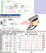
Choke-input filter voltages are not intuitive. They may be worked-out with a pencil. PSUD makes nice pictures.
The RMS voltage across the choke is 200V (I missed that in this image). This is well within spec.
The voltage -across- the choke varies from -400V to +243V. But the right end sits at a near-steady 390V DC. So the left end swings from near zero to +640V.
Will the 640V peak arc-over from the hot end of the winding to core and frame and chassis? The 2kV rating says this is OK, at least short-term. (Also Lundahl knows what you are doing and knows how to wind a choke which won't blow-up in customers' hands.)
Long-term (decades) the insulation breaks-down as the RMS of the wave. Unsurprisingly the RMS from the hot end of this winding to ground is 390V. Since most modern transformer/choke tape is good for 500V for a very long time, and Lundahl probably double-wraps windings which may go into high voltage gear, I would not worry.
Attachments
I do that with all my HV supplies. (1kv +)a 1kv megger will show you if the choke has enough insulation resistance to stand 700 volts dc..
otherwise, you can also put that choke in the negative leg if you feel iffy...
..
that 700 volts quickly dropped to a lower dc voltage under load...
you can check for that in your actual build...
the dc resistances in both the primary winding of the traffo and the secondaries ensure that the theoretical 700v will never happen in real life..
you can check for that in your actual build...
the dc resistances in both the primary winding of the traffo and the secondaries ensure that the theoretical 700v will never happen in real life..
I do that with all my HV supplies. (1kv +)
good practice....
I am trying to build a choke input filter similar with the schematic below. The LL1651 has 500Vrms output, after rectifier it's about 700v peak. however the LL1638 has the following limitation:
Max. ripple voltage at rec. DC current 300v rms.
with this limitation, will 700v damage the choke? I am not going to pull all of
the 200ma DC from the choke but still worried. where I missed?
I doubt it will be a problem, but I don't know your load so can't really say. The voltage (as noted, below 1kV in this circuit) won't be a problem though.
What can be a problem? Some chokes, under load can make noise. They buzz. It's annoying. Truly bad. That buzzing noise can even come out of your speakers if you are unlucky and your layout allows it.
I used Lundal chokes many times. They are built well and wound so cleanly with great insulation. They are so nice and quiet. 🙂
Even the LL1638 can work for choke input if the load is not too high. Hammond however...
Ian
Last edited:
Vripple rms = Idc load/(6.28*120Hz*C in uf)
so here we see that ripple voltage is directly proportional to load current, the higher the load current, the higher the ripple voltage...inversely proportional to Capacitor value, the higher the capacitance the lower the ripple...
so here we see that ripple voltage is directly proportional to load current, the higher the load current, the higher the ripple voltage...inversely proportional to Capacitor value, the higher the capacitance the lower the ripple...
- Home
- Amplifiers
- Tubes / Valves
- Help before I (may) damage the chokes