Hi All!
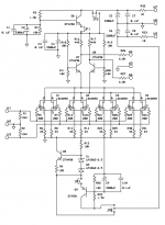
I want to build a phono amp for my system and so far the Pearl seems the best choice for me. The only problem is that it is a single ended circuit. So, I converted the circuit to the balanced one, based on several schematics posted on this forum.
By no means, this is an attempt to improve the amplifier performance. I just wanted a balanced phono amp because all the components in my system are balanced.
The schematic is for one cascade only. I want to make a PCB for the circuit which is shown on the picture. I will use two modules connected in series with RIAA network between them.
I really do appreciate if you guys look at the topology and point out if there are any mistakes there. I don't want to order PCBs and then discover that I made some stupid mistake. I am not worried much about component values at this point, because I will tweak them later.
Thanks a lot 🙂
Attachments
Sorry, but why don't you just use an unity gain inverter? You would avoid all those additional double-fets; the same was used in the Ono.
Cheers, Hannes
Cheers, Hannes
Thanks, Hannes
I am little bit confused, double fets are the main gain devices there. How can I substitute them with unity gain buffer?
I will look at Ono schematics. Thanks.
🙂
I am little bit confused, double fets are the main gain devices there. How can I substitute them with unity gain buffer?
I will look at Ono schematics. Thanks.
🙂
Today has been a rather trying day, so perhaps I'm missing something...or perhaps several somethings. Can you explain how you see the circuit working?
JP2 turns the circuit off? Allows for regulated/unregulated rail comparisons? Changes the rail voltage?
JP1 probably relates to JP2 I'm guessing, but again it depends on what you intend JP2 to accomplish.
It appears that Q9 (should Q9 be a ZTX550?) is intended to be a regulator for a negative rail...but there's nothing that needs a negative rail. Assuming that Q5 is intended to be a current source, there's a problem in that it dumps directly to ground via the connection beneath R6. For that matter, it wouldn't hurt to have a cap to ground at the emitter of Q9.
Etc.
Or maybe I just need to get some sleep. Or something.
Grey
Thanks Grey.
I guess I was tired too when I was drawing the schematics. The ground simbol below R6 should not be there and C9 and R15 should be grounded of course.
Nothing special about jumpers. I just wanted to have an option to disconnect Q6 and/or Q9 capacitance multipliers and use circuit without them.
I'll post corrected picture soon.
Again, thanks a lot 🙂
@Irakli: I mean you can add a unity gain inverter to the original pearl; thus you still only need 1x 2SK389 per channel.
Cheers, Hannes
Cheers, Hannes
Generating a balanced signal at the output is not the same thing as having a balanced circuit.
Grey
Grey
Of course! This is just a simple solution and its only benefit being noise cancelation in the following interconnects. However I don't see a clear advantage in canceling the pure 2nd harmonic distortion character of the pearl by balancing it.
That should give in my opinion quite strong 3rd harmonics which are far more unpleasant.
Cheers, Hannes
That should give in my opinion quite strong 3rd harmonics which are far more unpleasant.
Cheers, Hannes
Canceling 2nd order harmonics doesn't raise 3rd order harmonics. Okay, the "balance" between them changes, but the total amount of distortion decreases, and that's an advantage.
I am listening to the Pearl Amp second day now and I am noticing that it distorts sound little bit. 
For the lack of the better word, it sounds very “Transistor-like”. I suspect that THD may be high, but I have no means to verify that.
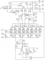
I measured all DC voltages and they seem fine to me. These voltages are shown on attached picture. I am using two cascaded identical sections with RIAA network between them. Measured Gain for each section is 27 and Vout (between hot and cold) is 11V before the clipping. Such a high output voltage looks strange to me because Q7 and Q8 should saturate well before the output reaches 11V. Nevertheless, that’s what I see on the scope.
I really do appreciate if somebody could look at the voltages on the attached schematic and recommend any changes. Will it help if I reduce the current and bring collectors of Q7 and Q8 at +21V?
Thanks a lot
For the lack of the better word, it sounds very “Transistor-like”. I suspect that THD may be high, but I have no means to verify that.
I measured all DC voltages and they seem fine to me. These voltages are shown on attached picture. I am using two cascaded identical sections with RIAA network between them. Measured Gain for each section is 27 and Vout (between hot and cold) is 11V before the clipping. Such a high output voltage looks strange to me because Q7 and Q8 should saturate well before the output reaches 11V. Nevertheless, that’s what I see on the scope.
I really do appreciate if somebody could look at the voltages on the attached schematic and recommend any changes. Will it help if I reduce the current and bring collectors of Q7 and Q8 at +21V?
Thanks a lot
Attachments
Hi all 🙂
Little experimentation helped. I reduced the total current to 29.9mA, by increasing R9 from 100 to 142 ohms (see picture in a previous post). This way each FET is running at 3.74mA.
Now the amp sounds really nice and I have no complaints whatsoever.
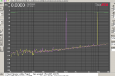
I also built inverse RIAA network to test the phono amplifier using TruRTA software as a spectrum analyzer.
The results are represented on an attached picture.
(green trace - freq. response. Purple and yellow traces - 1khz and 10Khz sine waves Respectively).
I am very pleased that I can't see any harmonic distortion.
Little experimentation helped. I reduced the total current to 29.9mA, by increasing R9 from 100 to 142 ohms (see picture in a previous post). This way each FET is running at 3.74mA.
Now the amp sounds really nice and I have no complaints whatsoever.
I also built inverse RIAA network to test the phono amplifier using TruRTA software as a spectrum analyzer.
The results are represented on an attached picture.
(green trace - freq. response. Purple and yellow traces - 1khz and 10Khz sine waves Respectively).
I am very pleased that I can't see any harmonic distortion.
Attachments
- Status
- Not open for further replies.
- Home
- Amplifiers
- Pass Labs
- Help - Balanced Pearl Phono