Hi all,
I just brought a second hand Audiostatic ES-100, but both speakers have a low level volume and I can hear distortion in low frequencies.
I am planning to replace the diaphragm.
Can somebody guide me to take the electrostatic panel out from the frame?
I have taken the bottom, upper and electronics mdf parts, but I have a problem when I tried to take both side mdf frames apart.
It looks the electrostatic panels glued to the both side frames.
Should I just force it or is there any other way to take the panel out from the side frames?
Thank you in advance for your help.
Peter
Yes you have to apply some force here to break the glue bonds. Try to push (hammer) a long small screwdriver in between the panel and the mdf and use it as a lever. Should be fairly easy to separate them that way. They are glued together with dots of glue every 10 cm or so, but the glue is not very strong.
Same applies for separating the two stators, they are glued together as well using some kind of silicone based glue. Just put a thin but strong knife in between and push it all along the perimeter of the panel.
good luck!
Same applies for separating the two stators, they are glued together as well using some kind of silicone based glue. Just put a thin but strong knife in between and push it all along the perimeter of the panel.
good luck!
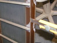
Done it.
I have managed to take the panel out and also take the panel apart with a little bit tears and blood. (tears because I managed to create scratch mark on the mdf frame and blood because I also managed to cut my finger.. lucky it wasn't deep") )
)
next challenge.... to clean the panel.
Do you know what I can use to clean the panel from glue residue? alcohol?
Thanks
I have managed to take the panel out and also take the panel apart with a little bit tears and blood. (tears because I managed to create scratch mark on the mdf frame and blood because I also managed to cut my finger.. lucky it wasn't deep
)next challenge.... to clean the panel.
Do you know what I can use to clean the panel from glue residue? alcohol?
Thanks
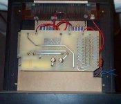
ES100 Manual and/or Circuit Diagram
Hi,
I have made some tweaks to make my ES100 sound better and the improvement is major! But for the next step I need to take them apart. Anyone with a circuit diagram you could share/publish or if available a service manual?
Thanks,
Ulf
PS! If any is interested I could describe my tweaks. DS!
Hi,
I have made some tweaks to make my ES100 sound better and the improvement is major! But for the next step I need to take them apart. Anyone with a circuit diagram you could share/publish or if available a service manual?
Thanks,
Ulf
PS! If any is interested I could describe my tweaks. DS!
Anyone know what the stock diaphragm coating is?
I have a friend with two pair of Audiostatics that is complaining that the output of the lower half of a pair of speakers is dropping in level (over a long time now...)
As far as I know there is nothing special in the schematic of the driver board... they use two xfmrs from the wall wart to boost the HV AC level up before dumping it into the usual multiplier.
(My friend does not have a HV supply problem, btw...)
Afaik they don't actually use the patented driver circuit at least in the panels that have a woofer and the "full range" panel together...
_-_-bear
PS. please do describe ur tweaks!!
Hi,
The ES100 is simple indeed.
The ES200R and 300R have a mirror drive interface which boost low frequency output to compensate for the destructive phase cancellation.
The easiest way to improve the es100 is to use thinner foils. The original is at least 6 micron thick.
You can play with the input cap. as well.
Some people even got the cap. completely removed.
Tweaks on the way
At the moment I'm in the process of modifying them (again), but give me a couple of weeks and I will be back with a description supplied with photos. A tip until then is to try to make the frame as rigid as possible.Originally posted by bear PS. please do describe ur tweaks!! [/B]
I think I got that tip from Ben Peters himself ten years ago and I have run mine ever since with that cap bypassed.Originally posted by MJ Dijkstra Some people even got the cap. completely removed. [/B]
thanks, film, not foil.
In case of removing the input cap you should check the DC-offset voltage of your amplifier. While most modern amps do have low dc-offset (less than ^ 10 mV), there might be amps with higher voltages. As the DC-resistance of the step-up trannie is rather low even a small dc-offset can make a rather high current, partially saturating the core of the transformer(s).
The frame of the es100 is not the stiffest. It is also very long, prone to vibrations.
Improvements can be made here as well but difficult without changing the original cosmetics.
The smaller es200 is much more rigid.
Improved new film?
What film did you use and how did you coat it?
MJ Dijkstra said:The easiest way to improve the es100 is to use thinner film. The original is at least 6 micron thick.
What film did you use and how did you coat it?
Re: Improved new film?
Hi,
I used a custom made tensilized Mylar® film of 4 micron 'thickness', proprietary fluid simply brushed on
Ulf Eliasson said:
What film did you use and how did you coat it?
Hi,
I used a custom made tensilized Mylar® film of 4 micron 'thickness', proprietary fluid simply brushed on
jam said:Schematic for the ES-50. Similar and might be of use..
Jam
I think the schematic is wrong as it shows the electrical segmentation of the stators as a parallel segmentation while it is in series!
Follow up question on Coating Fluid
Could you specify the fluid you used? Brand? What kind? What use is it made for? To get the correct conductivity and equally spread over the whole film is a delicate balance. Quad used a graphite powder attached to the film only by static electricity and I’m trilled to learn about a better alternative. … or is the film you are talking about conductive by itself?
MJ Dijkstra said:... proprietary fluid simply brushed on
Could you specify the fluid you used? Brand? What kind? What use is it made for? To get the correct conductivity and equally spread over the whole film is a delicate balance. Quad used a graphite powder attached to the film only by static electricity and I’m trilled to learn about a better alternative. … or is the film you are talking about conductive by itself?
Calvin said:...the midlow-strips to the left and right of the HT-strip are wired via resistor.
Are these 2x4x47kΩ resistors metal film? If not, they are in the signal path so, it would be interesting to hear if anybody replaced them.
Calvin said:Hi,
hey Martin, haven´t You seen the 0-Ohm resistance in series?
How could it be wired different?
The HT-Strip is wired directly, the midlow-strips to the left and right of the HT-strip are wired via resistor. Can´t see anything strange here.
jauu
Calvin
Nice joke about 0 resistance but I think you simply didn't understand my point.
I have seen the audiostatics from the inside myself, there is only one wire per stator (no split-up), so the different sections of a single stator are connected in series, not parallel as in the picture. I have not talked about the HT-strip. Hope you understand my point now.
Picture of a ES100 (taken from http://www.nacl.de/esl/ google image search is your friend)
From the looks of it, the circuit diagram seems to be correct.
From the looks of it, the circuit diagram seems to be correct.
Attachments
- Status
- This old topic is closed. If you want to reopen this topic, contact a moderator using the "Report Post" button.
- Home
- Loudspeakers
- Planars & Exotics
- Help, Audiostatic ES-100