You said that the power trace was inside the board. If that's the case, the blackened area may be between outer layers of copper which would make it difficult to see.
If you want to confirm that there is supposed to be a connection between the points, order the service manual.
If you want to confirm that there is supposed to be a connection between the points, order the service manual.
+12V should go to the fuse holders, then to the filter inductors, then to the main transformer and then to the center leg of all PSU MOSFETs. A multimeter should show a 0 ohm path.
BTW: This new generation of amplifiers employing International Rectifier's DirectFET transistors in BGA-style packages sandwitched directly between the PCB and the heatsink is going to be really unreliable due to vibrations and thermal stress. The PCB is also stressed and hole plating in vias tends to fail resulting in intermittent open circuits and little chances for repair. Life expectancy is probably 2 o 3 years, while classic designs with leaded transistors tend to be forever...
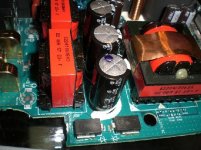
In fact, you may easily discover that your open circuit is due to fused hole plating in PCB vias (those metalised holes used to connect top and bottom side tracks). Vias are abused in that kind of power designs, they get easily damaged with too high current, too much PCB bending or too much PCB expansion and contraction due to thermal cycling (particularly when they are not filled with solder as they used to be in the past).
BTW: This new generation of amplifiers employing International Rectifier's DirectFET transistors in BGA-style packages sandwitched directly between the PCB and the heatsink is going to be really unreliable due to vibrations and thermal stress. The PCB is also stressed and hole plating in vias tends to fail resulting in intermittent open circuits and little chances for repair. Life expectancy is probably 2 o 3 years, while classic designs with leaded transistors tend to be forever...
In fact, you may easily discover that your open circuit is due to fused hole plating in PCB vias (those metalised holes used to connect top and bottom side tracks). Vias are abused in that kind of power designs, they get easily damaged with too high current, too much PCB bending or too much PCB expansion and contraction due to thermal cycling (particularly when they are not filled with solder as they used to be in the past).
Yep, I do believe you are right. I think that is what happened to mine is the layers unfused. But mine is from to much reverse current. not vibration. I have the new Ice componets from B & O, And they don't even have a heat sink. Very Scary.
Anyway, Perry I have another PDX 2.150 has the same board, so I took it apart and I am getting 0-1ohm between B+ and Inductor terminals. So you are right. And I really appreciate all your help!!!
I wish I was half as knowledgable as you on these circuits. Oh well I'm learning. Again THANKS!
And Eva, I Thank you as well....
Anyway, Perry I have another PDX 2.150 has the same board, so I took it apart and I am getting 0-1ohm between B+ and Inductor terminals. So you are right. And I really appreciate all your help!!!
I wish I was half as knowledgable as you on these circuits. Oh well I'm learning.
Again THANKS!And Eva, I Thank you as well....
Oh yea, I did mean to ask what Kind of wire or connector should I solder the board with? I'm guessing it has to handle some current since it is at the power connectors? It Has 2- 30amp fuses.
For testing (to determine if there are other problems), you can use a short piece of wire as small as 16g. The 10A fuse will protect the 16g wire in case there is another problem. For the final repair, you could use two 12g wires.
Remember... Clamp all power semis to the sink before applying power.
If the fuse blows, you may have shorted reverse protection diodes. I didn't see them in the photos. In some amps, the intrinsic diode in the PS FETs serves as reverse protection.
Remember... Clamp all power semis to the sink before applying power.
If the fuse blows, you may have shorted reverse protection diodes. I didn't see them in the photos. In some amps, the intrinsic diode in the PS FETs serves as reverse protection.
I've never seen zeners (transient surge suppressors, in this case) used as RP diodes but it it's possible that's how they're being used here. Generally RP diodes are connected directly across B+ and ground (very near the terminal block/fuse holder).
The 'forward' voltage on these is greater than the forward voltage of the FET's intrinsic diode so they wouldn't be able to do much unless the B+ voltage reached 30v (if they're connected across B+ and ground).
If you read 0 ohms across them, they're shorted (or the FETs are shorted).
The 'forward' voltage on these is greater than the forward voltage of the FET's intrinsic diode so they wouldn't be able to do much unless the B+ voltage reached 30v (if they're connected across B+ and ground).
If you read 0 ohms across them, they're shorted (or the FETs are shorted).
Hey Perry, Just wanted to let you know it fired up. Lights came on. I haven't wired it up to music yet, but I think it will be fine. I really appreciate all your help. Thank you. Randy
gee, I go away for a couple of days, and all the problems are solved !!!
well done on the troubleshooting 🙂
one reason these amps fail - as mentioned - is thermal cycling. It's quite normal for them to reach 50+ degrees C internally, and get quite hot externally.
It's a pity, as these could be fantastic amps if they had more aluminium and less air inside them.
well done on the troubleshooting 🙂
one reason these amps fail - as mentioned - is thermal cycling. It's quite normal for them to reach 50+ degrees C internally, and get quite hot externally.
It's a pity, as these could be fantastic amps if they had more aluminium and less air inside them.
- Status
- Not open for further replies.
- Home
- General Interest
- Car Audio
- Help? Alpine PDX 4.150 Dead of reverse polarity...