Hi everyone, first of all, I'm a strong enthusiast, not a technician or engineer.
I have a hi-end CD player with an excelent DAC and analog section. It's a really fantantic CD player, very silent, dynamic with excelent detail.
I would love to know if it's possible to add a digital INPUT to it. So I can use the DAC and analog section by connecting an external digital transport (SPDIF).
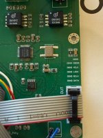
I have a digital input I2S module but I don't know if it's usable here. You can see the attached photo of that module.
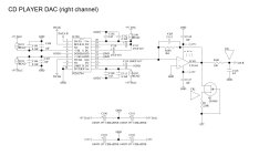
I'm also posting the schematic of the digital section of the CD player and the DAC (just one channel).
Any help or input would be much apreciated!
Thanks and greetings from Lisbon
Andre
I have a hi-end CD player with an excelent DAC and analog section. It's a really fantantic CD player, very silent, dynamic with excelent detail.
I would love to know if it's possible to add a digital INPUT to it. So I can use the DAC and analog section by connecting an external digital transport (SPDIF).
I have a digital input I2S module but I don't know if it's usable here. You can see the attached photo of that module.
I'm also posting the schematic of the digital section of the CD player and the DAC (just one channel).
Any help or input would be much apreciated!
Thanks and greetings from Lisbon
Andre
Attachments
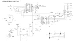

According to the schematic, the digital section of your CD player is based on the DIR1703 chip. The Texas instruments datasheet states that pin 20 of this chip is a 5V tolerant CMOS level input that also accepts a standard SPDIF signal. You may try to lift the R48 (22 ohm) resistor to disconnect pin 20 from the U12 isolator chip, and apply the external spdif signal to pin 20, after converting it to CMOS logic levels.
As alternative, the external SPDIF signal may be applied to pin 5 (spdif input) of the connector CN1, after disconnecting it from the CD player logic board, but then you need the U12 datasheet to check what logic levels are accepted at pin 1. Or if you have a oscilloscope, just measure the signal at pin 1 of U12 while a disk is playing to find out.
As alternative, the external SPDIF signal may be applied to pin 5 (spdif input) of the connector CN1, after disconnecting it from the CD player logic board, but then you need the U12 datasheet to check what logic levels are accepted at pin 1. Or if you have a oscilloscope, just measure the signal at pin 1 of U12 while a disk is playing to find out.
This appears to be the datasheet for U12: https://mm.digikey.com/Volume0/opasdata/d220001/medias/docus/817/ISO150_Rev2008.pdf
Hi Ken! Not at all. It works really well. I also have a Cambridge 851N streamer with some mods that works really well but the DAC and analog section of my CD player is superior.
According to the schematic, the digital section of your CD player is based on the DIR1703 chip. The Texas instruments datasheet states that pin 20 of this chip is a 5V tolerant CMOS level input that also accepts a standard SPDIF signal. You may try to lift the R48 (22 ohm) resistor to disconnect pin 20 from the U12 isolator chip, and apply the external spdif signal to pin 20, after converting it to CMOS logic levels.
As alternative, the external SPDIF signal may be applied to pin 5 (spdif input) of the connector CN1, after disconnecting it from the CD player logic board, but then you need the U12 datasheet to check what logic levels are accepted at pin 1. Or if you have a oscilloscope, just measure the signal at pin 1 of U12 while a disk is playing to find out.
Hi pcan! Thank you your input!!
The DAC schematic is from, I believe, the Plinius CD-101. The digital section schematic, however, is very unusual for a CD player. Featuring, as it does, an S/PDIF input path. That schematic shows a digital signal path which begins with a DIR1703 S/PDIF input receiver, then goes to a DF1706 digital filter, then to a bus switch/multiplexer chip before being sent to the DAC. However, the digital section schematic doesn’t show a means for the CD drive to send its recovered signal data to the input of the DF1706 digital filter chip. In fact, the digital schematic looks like it belongs to some stand-alone DAC, not to a CD-player.
Anyhow, connector CN1, provides the means to easily add an S/PDIF input interface circuit. Which, at its most basic, is a 75 ohm shunt impedance matching resistor. However, FIRST, verify that the digital section schematic belongs to your CD-player.
Anyhow, connector CN1, provides the means to easily add an S/PDIF input interface circuit. Which, at its most basic, is a 75 ohm shunt impedance matching resistor. However, FIRST, verify that the digital section schematic belongs to your CD-player.
This is something I think would be cool to do to older CD players. I'd love to have digital input on one of my Rotels.
You may not have realized it, but you already have a circuit to switch two digital (SPDIF) signals to the input of the DAC.
Should work like this, but check by yourself before starting to work! The orientation of the data sheet and the CD's schematic seem somehow flipped because you can program any input to be an output, too. So don't take my numbers for real, but the principle should be made clear:
U12 is such a SPDIF switch, you only have to use the second channel too. Then you can switch off the CD drives output from the DAC and instead switch on the alternative source on pin 28. The contacts 15 and 28 at U12 are tied to ground, you should be able to free them up and connect an SPDIF input and a switching input plus connection to DAC in SPDIF. The output 15 only needs a 22k resistor similar to R48. Last is to make the +5V to 3 switchable to 26 alternating.
It is all in the data sheet https://mm.digikey.com/Volume0/opasdata/d220001/medias/docus/817/ISO150_Rev2008.pdf
Last edited:
Hi turbowatch! That’s a great help!!!! And I will definitelly follow your advice.
I’m still working on the project due to the fact that the DAC board on my CD player is configured for 44.1Khz on the DIR1703. I have to make some changes on the Digital
Audio Interface side to allow higher resolutions.
I’m still working on the project due to the fact that the DAC board on my CD player is configured for 44.1Khz on the DIR1703. I have to make some changes on the Digital
Audio Interface side to allow higher resolutions.
- Home
- Source & Line
- Digital Source
- HELP - Adding digital input to CD player