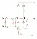
I am experimenting with adding a Current Mirror to a Diff pair circuit. I want to understand how to calculate the load resistors. So for example I have an existing circuit as shown. If I add a CM, how do I calc the new resistor values for R22 & R23??
Attachments
Last edited:
The current mirror is the load.
You tap off the collector below the CM to feed the VAS.
The CM can use zero ohms for the two upper resistors. but it does not work well. I think IC opamps use near zero ohms because resistors add to the IC cost.
The emitter resistors can be any value from 1r0 to 10k, but most adopt something in the range 100r to 1k
Read S.Groner.
He shows that the CM works very well with R>470r
the resistors also help to reduce the effects of the transistors having some degree of mismatch.
ICs generally don't use and don't need the resistors because of the ability to match transistors so tightly.
mlloyd1
ICs generally don't use and don't need the resistors because of the ability to match transistors so tightly.
mlloyd1
I have been reading sloane and i need to go back and re-read but i thought there was mention of dropping 50mv? But how do you calc that?
ohms law is your friend.
🙂
you know the current in each transistor of the diff pair - when the pair is balanced, it would be half the tail current you set with the current sink.
then you choose a corresponding resistor that has 50mV across it when said current flows through it.
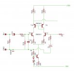
and, by the way, you take the output (current) from the collector of the mirror transistor, not the emitter resistor as you have shown ...
mlloyd1
🙂
you know the current in each transistor of the diff pair - when the pair is balanced, it would be half the tail current you set with the current sink.
then you choose a corresponding resistor that has 50mV across it when said current flows through it.
and, by the way, you take the output (current) from the collector of the mirror transistor, not the emitter resistor as you have shown ...
mlloyd1
As im thinking through it, that makes sense. If...50mv is the target. Then 50 ohms should be correct for 1ma
{50mV across the emitter degeneration resistors} is one guy's opinion of how much insensitivity-to-PNP-mismatch, is typically needed. Another guy's opinion, mine, is: you need much more. I aim for at least 200mV and if the circuit will tolerate more (some circuits will!), I drop even more voltage across the emitter resistors.
Those able to run SPICE simulations are invited to simulate a PNP current mirror with 2.0mA flowing in the input leg, variable emitter resistors, and a 5 millivolt voltage source in series with one PNP transistor base but not the other. (This voltage source simulates transistor mismatch.) What's the current in the output leg, as you simultaneously vary both emitter resistors from 2 ohms (2mV drop) to 500 ohms (1000mV drop)? What does it mean?
Those able to run SPICE simulations are invited to simulate a PNP current mirror with 2.0mA flowing in the input leg, variable emitter resistors, and a 5 millivolt voltage source in series with one PNP transistor base but not the other. (This voltage source simulates transistor mismatch.) What's the current in the output leg, as you simultaneously vary both emitter resistors from 2 ohms (2mV drop) to 500 ohms (1000mV drop)? What does it mean?
Last edited:
Your conection to th next stage is in the wrong place. It should be on the collector of the transistor, it's the load.
@Mark, isn't the purpose of the degeneration (Re) to swamp the effect of differing (re) in the mirror devices?
Vdrop on the CM emitter resistor should be at least 200mV
If your VAS can provide more voltage drop, then aim for >500mVdrop.
A double EF VAS provides ~1300mV and would suit a 600mV Vdrop on the emitter resistors if you use a very good near saturation transistor. BC560, or BC337 (if I remember correctly).
If your VAS can provide more voltage drop, then aim for >500mVdrop.
A double EF VAS provides ~1300mV and would suit a 600mV Vdrop on the emitter resistors if you use a very good near saturation transistor. BC560, or BC337 (if I remember correctly).
Voltage across D7 compensates for the Vbe of T6
The voltage drop across R16, 390 Ohm is about 0.6 V, the same as the voltage across D9.
This defines a current of 0.6/0.390 = 1.54 mA in the long tail pair.
If the currents in transistors T8-T7 of the input pair are well balanced, the voltage across R22 or R23 should be around 1.54/2 * 2.2 = 1.7 V. It is a quite unusual value here.
No help is possible without knowing the right side of the circuit.
@Mark, isn't the purpose of the degeneration (Re) to swamp the effect of differing (re) in the mirror devices?
Not in discrete transistors with huge (compared to IC transistors) emitter areas and tiny (compared to IC transistors) series resistances. In discrete designs the purpose of emitter degeneration is to swamp the effect of different VBEs in the mirror devices.
Have a look at the LTSPICE model parameter values for extrinsic emitter resistance of discrete transistors, they are tiny. For the 2N3906: 0.1 ohm. For the ZTX951: 0.02 ohms.
{50mV across the emitter degeneration resistors}
So to be clear, are you talking about R22 and R23 in my photos?
Your conection to th next stage is in the wrong place. It should be on the collector of the transistor, it's the load.
Wow I really did draw that all wrong. that's what I get for trying to hurry in the morning.
Attachments
Voltage across D7 compensates for the Vbe of T6
The voltage drop across R16, 390 Ohm is about 0.6 V, the same as the voltage across D9.
This defines a current of 0.6/0.390 = 1.54 mA in the long tail pair.
If the currents in transistors T8-T7 of the input pair are well balanced, the voltage across R22 or R23 should be around 1.54/2 * 2.2 = 1.7 V. It is a quite unusual value here.
No help is possible without knowing the right side of the circuit.
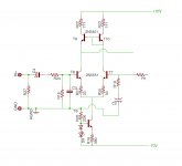
Here is the rest of the circuit minus the output devices.
Attachments
Schematic in post #15 incorrect. Correct schematic attached here. Resistors in series with the emitter legs of the current mirror transistors, are the "emitter degeneration" resistors. In this picture they are named R22 and R23.
_
Thank you for correcting that.
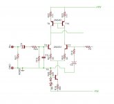
Remove D8 and D12 from the base of the PNP second stage amplifying transistor in post #16.
those are in the original design. I wanted to experiment based on this schematic. are they not needed if I add the Current Mirror?
Attachments
- Status
- Not open for further replies.
- Home
- Amplifiers
- Solid State
- Help Adding a Current Mirror to a Diff Pair Res Calc