Hi guys.
The left channel of my power amp RОТЕL has a high DC offset (13-14V).
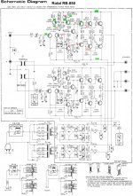
I apply a scheme.
In red are the higher voltages measured by me.
Transistors Q 609 and Q 615 have been replaced, but without effect.
Every help will be appreciated!
Greetings!
The left channel of my power amp RОТЕL has a high DC offset (13-14V).
I apply a scheme.
In red are the higher voltages measured by me.
Transistors Q 609 and Q 615 have been replaced, but without effect.
Every help will be appreciated!
Greetings!
Attachments
Check around Q605. You have 11 volts as a reverse bias condition across the B-E junction. That voltage in itself should limit lower than that to around 7 volts I would have thought under a fault condition.
Q611 should be turned fully on in this fault condition and be trying to pull its collector voltage down toward the negative rail. Check the B-E voltage across the junction to see if this is happening.
(I assume all four 0.22 ohms are OK and that the four output transistors are also OK)
.
Q611 should be turned fully on in this fault condition and be trying to pull its collector voltage down toward the negative rail. Check the B-E voltage across the junction to see if this is happening.
(I assume all four 0.22 ohms are OK and that the four output transistors are also OK)
.
This +11V on the feedback node switches off Q605, pushing all current from Q603 through Q601 forcing Q611 full open (in accord with Mooly). But the collector of Q611 is not pulled to the negative rail (notice the error in the drawing: there is no connection dot!). It tries to (indeed check the voltage on the base of Q611), but there's more current 'leaking' from the positive rail then it can sink. The bias current should be around 6mA, and the bias circuit around Q613 is still working with almost the desired voltages. One can assume now Q690 is also doing fine. That leaves us with Q615 (already replaced) and Q619 or Q623.
Most probable candidates.
Most probable candidates.
Thanks for the answers
I made many measurements including desoldering Q619 and Q623 but without success.
Maybe hard to believe, but the problem was in D601 (drop 20 mV in both directions)
After his replacement everything is fine!
Thanks again!
Be healthy!
I made many measurements including desoldering Q619 and Q623 but without success.
Maybe hard to believe, but the problem was in D601 (drop 20 mV in both directions)
After his replacement everything is fine!
Thanks again!
Be healthy!
Ah... we all are tricked by the electronics and consider the diodes as immortal.
So the current source was crippled and the feedbackloop was not able anymore to correct this huge offset. This is a very valuable experience and important for the design of such circuit elements.
Thanks for all the effort and informing us lim0nade!
edit:
1N4148: 50V
When switching on the amp, a spike from the net can invoke a >>50V drop across the first in line, being D601 and bang.
Use at least 100V diodes in circuits running +/- 42V!
Last edited:
Ah... we all are tricked by the electronics and consider the diodes as immortal.
So the current source was crippled and the feedbackloop was not able anymore to correct this huge offset. This is a very valuable experience and important for the design of such circuit elements.
Thanks for all the effort and informing us lim0nade!
edit:
1N4148: 50V
When switching on the amp, a spike from the net can invoke a >>50V drop across the first in line, being D601 and bang.
Use at least 100V diodes in circuits running +/- 42V!
So I'm going to show some ignorance here. Q601, D601, D603, R605 and R607 make a 1.28 mA current source.
I've used this configuration many times. Q607, Q609, R613 and R615 also make a current source, this time 6 mA.
My ignorant question is, how is one version superior to the other and why? Temperature compensation, speed?
Merry Christmas and thanks
G²
Both current sources are interchangable (imho), but have a different 'dynamic' (electronically, not sonic).
The diff-pair cs is the classic config as a static current mirror (Q603-D603) and reference voltage sourse (D601) put over R605, rendering into the rightly calculated 1.28mA.
These kind of current sources are very, no, extremely reliable, save the lottery-price exception...
The Q607-Q609 cs is a self adjusting type rendering into an ultimate pinched balance. These kind of cs's are known from the germanium-age.
As said, they're interchangable but which is better, or which is preffered in what situation? Temperature and not-static dc characteristics ('speed') kick in now.
The cmcs has a 'slower' slope to reach the end value, the pinched cs is almost immediate.
But faster is not better here: by taking time for the input diff to settle - to come up steam - the current through Q611 is raised in a relaxed fashion, and so the bias, and so the end stage. No shocks at the output better, the feedback and it's loop have their own dynamic response when switching on or off. It is very pleasant if the 607-609 combo is stable already and does not contribute more variables to the (startup and shut down) equations. Even better to use two different topologies here, or the same but with different timing (an extra cap to slow one down a bit).
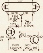
Earlier posted on this platform elsewhere, the Sony Esprit current source is a superior one - the bjt and fet compensates mutually and the zener assures precise start and stop. R210 determines the cs current value. Serving flawlessly over thirty years in my TA-E86B now.
The diff-pair cs is the classic config as a static current mirror (Q603-D603) and reference voltage sourse (D601) put over R605, rendering into the rightly calculated 1.28mA.
These kind of current sources are very, no, extremely reliable, save the lottery-price exception...
The Q607-Q609 cs is a self adjusting type rendering into an ultimate pinched balance. These kind of cs's are known from the germanium-age.
As said, they're interchangable but which is better, or which is preffered in what situation? Temperature and not-static dc characteristics ('speed') kick in now.
The cmcs has a 'slower' slope to reach the end value, the pinched cs is almost immediate.
But faster is not better here: by taking time for the input diff to settle - to come up steam - the current through Q611 is raised in a relaxed fashion, and so the bias, and so the end stage. No shocks at the output better, the feedback and it's loop have their own dynamic response when switching on or off. It is very pleasant if the 607-609 combo is stable already and does not contribute more variables to the (startup and shut down) equations. Even better to use two different topologies here, or the same but with different timing (an extra cap to slow one down a bit).
Earlier posted on this platform elsewhere, the Sony Esprit current source is a superior one - the bjt and fet compensates mutually and the zener assures precise start and stop. R210 determines the cs current value. Serving flawlessly over thirty years in my TA-E86B now.
Attachments
in cases, when such unwanted DC offsets occurs just temporary and not permanent, the only possibility to isolate the source of the error is the splittingWell done
the stages for checking the independent operation.
As a first step I separate the output buffer darlington or triplet from the front-end (mostly LTP+VAS). The NFB resistor was now connected to the C or E of Vbe multiplier.
If DC offset isn't longer present for a longer period of time, one or more transistors of the output buffer are to replace.
Otherwise the LTP and the Vas stage are to separate for troubleshooting, which is a bit more complicated but unfortunately necessary in cases, if the DC offset sporadically and very rarely occurs, independent of temperature fluctuations and vibrations.
The output buffer should not be connected during this examination until fix the exact reason therefore.
Last edited:
Well just to defend my own line of reasoning here 🙂 when I posted earlier I took the voltages on the circuit in post #1 at face value and as such they actually do not show an issue with the current source.
If D601 was dropping only 20mv then the voltages shown (and that I assumed to be measured as correct) would have been very different.
The devil is always in the detail in fault finding 🙂
And that in no way detracts from lim0nade finding the issue it is just something that is so very very important when fault-finding and that is to gather as much evidence as possible before changing parts.
If D601 was dropping only 20mv then the voltages shown (and that I assumed to be measured as correct) would have been very different.
The devil is always in the detail in fault finding 🙂
And that in no way detracts from lim0nade finding the issue
it is just something that is so very very important when fault-finding and that is to gather as much evidence as possible before changing parts.- Home
- Amplifiers
- Solid State
- Help about High DC Offset