hi!
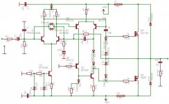
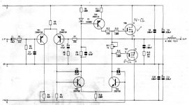
I decided to build one power amp (with 2sk135/2sj50)
which works in AB class with power of 60w in 8ohms.
In croatia this mosfets are pretty expensive so I'm
thinking about replacing this mosfets with irfp240/irfp9240.
I heard that these hexfets need Vbe multiplier.
I'm beginner in electronics so I'll be grateful if
somebody can tell me can i just replace this mosfets or
help me what i need to change in my scheme so i can put
irf devices.
here is the scheme:
Attachments
I am not sure but 2sk1058/2sj62 might do it, someone said they had used these in an amplifier that used the mosfets you mentioned and they were ok.
Check the data sheets first though.
Craig
Check the data sheets first though.
Craig
It is OK to use d-mosfets but with a Vbe or Vgs multiplier. It tends to be overly compensated with a Vbe multiplier and I usually use a small TO220 MOSFET as Vgs multiplier. You just need to be careful with the Vgs multiplier to make sure that you don't have a thermal runaway.
Hi,
What does D3 do? it seems it could be omitted.
V FETs must use a thermal compensator.
Drive to Q8 missing.
R1 is too big, try 680r and change C2 to 1nF to maintain rc time constant.
C7 & C8 could use a bigger decoupling cap in parallel, try 100uF+47nF.
What does D3 do? it seems it could be omitted.
V FETs must use a thermal compensator.
Drive to Q8 missing.
R1 is too big, try 680r and change C2 to 1nF to maintain rc time constant.
C7 & C8 could use a bigger decoupling cap in parallel, try 100uF+47nF.
Hi Andrew,
D3 is needed to increase the drop from the 40V supply to bias the next stage AND to provide Tcomp of that following stage. Otherwise Vacross the 1K5 resistors is only 0.63V, not enough!
D3 raises this to about 1.25V enough with one Vbe Tcomp to provide a stable 0.6V for the 47R tail resistor of the diff'l Vas so defining the operating current as 6.4mA per leg.
Hi mbonus,
To answer the thread question, you will need a higher bias, variable up to 8V for the IRFP240/9240 pair and include source resistors of maybe 0R47. These MOSFETs have a +ve tempco of around 3 times that of a BJT but off a much higher Vgs so % tempco is actually about half the compensation needed to track for a BJT. That's why a std Vbe multiplier overcompensates.
You can provide this in a few ways -
1. A standard Vbe multiplier with degrading R in the emitter leg.
2. A Vgs multiplier.
3. Standard Vbe multiplier for half plus variable resistor for other half bias.
4. string of diodes in thermal contact for 1/2 + variable resistor for other half bias chain.
Hope that helps
Cheers,
Greg
AndrewT
"Hi,
What does D3 do? it seems it could be omitted."
yes it could ,then youd need to adjust the colector resistors
cheers
"Hi,
What does D3 do? it seems it could be omitted."
yes it could ,then youd need to adjust the colector resistors
cheers
thanks andrew!
it will be much more easier to me
if somebody can draw in my scheme where
and how to connect this Vgs multiplier 🙂
so i can put irf-s.
(i tried to find 2sk1058/2sj62 but 2sj62
is also hard to find for me.)
thx!
it will be much more easier to me
if somebody can draw in my scheme where
and how to connect this Vgs multiplier 🙂
so i can put irf-s.
(i tried to find 2sk1058/2sj62 but 2sj62
is also hard to find for me.)
thx!
A Hafler DH120 delivered 60W/8R with a very similar circuit and the K/J outputs.
It ran on ±52V from a 36-0-36 transformer.
If you use the IRF parts the voltages will need to be even higher (unless you were intending to use a fully regulated supply).
It ran on ±52V from a 36-0-36 transformer.
If you use the IRF parts the voltages will need to be even higher (unless you were intending to use a fully regulated supply).
Hi mastertech!
I found this scheme in croatian electronic magazine "Majstor"
If somebody interested i can also put details of this amp
and how it can work in A class but with a larger heatsink...
Hi Amplifierguru!
thx for your explanation to me.
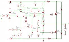
but I must ask you something more because,like I said,I am beginner.. 🙂
If I understand you good,I will get a higher bias if I use a Vbe(Vgs)
multiplier?
do I must use a higher voltages if I want to use irf parts like djk said?
(I also found your amplifier with irf parts with +/-30v and now I don't know what to build 🙂 ..I will also try to build your amp too,but i want to learn how to put this multiplier..)
I tried to put this Vbe multiplier so if somebody can tell me,am I on good way,
do I need to put something more,or remove and which values of resistors and
transistor do I need.
thx to anyone!
here is the picture:
I found this scheme in croatian electronic magazine "Majstor"
If somebody interested i can also put details of this amp
and how it can work in A class but with a larger heatsink...
Hi Amplifierguru!
thx for your explanation to me.
but I must ask you something more because,like I said,I am beginner.. 🙂
If I understand you good,I will get a higher bias if I use a Vbe(Vgs)
multiplier?
do I must use a higher voltages if I want to use irf parts like djk said?
(I also found your amplifier with irf parts with +/-30v and now I don't know what to build 🙂 ..I will also try to build your amp too,but i want to learn how to put this multiplier..)
I tried to put this Vbe multiplier so if somebody can tell me,am I on good way,
do I need to put something more,or remove and which values of resistors and
transistor do I need.
thx to anyone!
here is the picture:
Attachments
Remove D6 and D7. For IRFP substitutes you need about 6V between gates, D6 and D7 limit this to 1.4V.
You will get better results from IRFP240 + IRFP9140, if you use them without a resistor in series between sourse and output (this would be my recomendation).
Vbe multiplier is correctly drawn in principle but will be impractical in reality and even unsafe (if trimmer loses contact, the output stage will be destroyed because bias will be 'infinite').
I suggest using a Vgs multiplier instead. Use a small MOSFET, IRF510, 520 or similar. Connect D to where you now have C of your Vbe multiplier, S to where you now have E of your Vbe multipler transistor. From S to G connect a resistor of 12k ohm. From D to D connect a trimmer of 10k ohm and a resistor of 8.2k ohm in series. Connect wiper of trimmer to one of it's legs, and initially set it up so that the resistance is maximum. This will give you about 18k ohm from G to S. Also, connect 10u/16V and 0.1u foil cap in parallel, and then connect that in parallel with D - S of the Vgs multiplier MOSFET. Optionally, you can connect a non-inductive foil or even ceramic cap in parallel with D - G of the Vgs multiplier MOSFET. This cap should be on the order of 10-47nF.
The Vgs multiplier MOSFET MUST be in good thermal contact with the heatsink, preferably close to the IRFP240/9140, best in the middle between them (and of course electrically insulated from the heatsink).
If you wish to connect series resistors between S of the output transistors and the speaker output (cca 0.22 - 0.39 ohm), you may need to increase the top resistor in the Vgs multiplier to 15k ohm if you cannot get the proper idle current. This will be on the order of 50mA, perhaps more in the case with 0.22-0.39 ohms fitted, and possibly less without them, but without them it is a it more difficult to measure idle current (normally you just measure voltage across the 0.22-0.29 ohm resistors).
It is highly recomended that you power the driver stages (i.e. everythjing except the output transistors) with a voltage about 6-8V higher than the output transistors, possibly more if you use the source resistors (0.22-0.39).
A quick fix would be to insert a diode (1N4001 or similar) in the power line to the driver circuits on both the _ and - side, and a large-ish capacitor (470uF/63 in parallel with a good 1u foil) behind each diode. This will keep the driver stage voltage higher than the output during maximum power by preventing the power supply droop away from the driver stages.
hi ilimzn!
Thank You for details about my question.(Hvala! 🙂 )
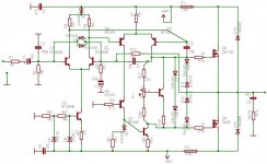
could you please look again my scheme which I corrected
so I can be sure it is alright now.
Did I remove right diodes?You said that i need to remove
D6 and D7 but You probably thought D7&D8.Am i right?
I also put source resistors because I can't find irfp9140..
If I understand you good,when I have source resistors i need
15k resistor between G and D,right?
Did I put electolytes into right place?
Thanks!
scheme:
Thank You for details about my question.(Hvala! 🙂 )
could you please look again my scheme which I corrected
so I can be sure it is alright now.
Did I remove right diodes?You said that i need to remove
D6 and D7 but You probably thought D7&D8.Am i right?
I also put source resistors because I can't find irfp9140..
If I understand you good,when I have source resistors i need
15k resistor between G and D,right?
Did I put electolytes into right place?
Thanks!
scheme:
Attachments
Dear Mbonus!
In the attachment there is an old and simple design with the same topology. The schema is good start-point, you can improve it yourself.
DJK!
The Hafler DH-120 doesn't uses the same circut. Yes, both has CCS, LTP, and mosfet output devices, but they are much different.
Here is the schema of the Hafler, you can compare it with Mbonus's design:
http://www.hafler.com/techsupport/pdf/DH-120_amp_man.pdf
Attachments
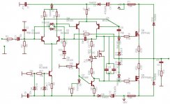
Hi M,
C11 & C12 should connect Vrail to Power Ground not to diode.
All your ground symbols are the same. It is better to have separate signal & power grounds, with 2 connections back to cental star earth.
anyone else,
C4(over two stages) & C5(Miller comp over VAS stage) seem to do the same thing, Hi freq roll off. Does M need both or one only? Which is better?
R1(15k) is still there creating 5db loss in sensitivity and extra avoidable noise. Does anyone else support reducing it to less than 1k0?
Hi Edl,
re post 18 schematic.
you show cascaded LTPs, but only the second has a current mirror. This topology is very common. Many have said that resistor load on the first diff pair is essential to good sound.
Have you any thoughts on the preferred loading on the second stage LTP regarding sound quality?
Are cascaded LTPs more or equally difficult to eliminate instability?
- Status
- Not open for further replies.
- Home
- Amplifiers
- Solid State
- help!ab class mosfet amp