I've finished building an SE 807 circuit with 6SJ& as driver. Can someone please explain why on one of the 807s cathode I'm reading 64 volts while on the other it is spot on at 21v (with 400 ohms as cathode bias)? Anode and screen voltages are the same as for the other valve (around 310v).
In my fault-finding trials I (a) swopped both output and driver valves and (b) isolated the problematic 807 from its driver stage but I still get the same high voltage reading on the cathode.
One other bizarre feature is that if I touch the grid leak resistor (1K) with the DVM probe there is a hefty spark on the output transformer!
I hope I can get some feedback which will lead me to solve this problem.
Thanks and regards to all.
Joe A

Sorry burnedfingers! Somehow the image is too large to post. I reduced with bad effect. I sent you an email for your address so I can send to you via my email. as I'm still having problems, can you reply to my personal email. Thanks for your patience.
sonata149 said:I've finished building an SE 807 circuit with 6SJ& as driver. Can someone please explain why on one of the 807s cathode I'm reading 64 volts while on the other it is spot on at 21v (with 400 ohms as cathode bias)? Anode and screen voltages are the same as for the other valve (around 310v).
In my fault-finding trials I (a) swopped both output and driver valves and (b) isolated the problematic 807 from its driver stage but I still get the same high voltage reading on the cathode.
This looks a lot like a case of a gassy 807. If there's 64V at the cathode with cathode bias, that means way too much current. If this isn't being caused by a leaky coupling capacitor (and there are some of those audiphool PiO capacitors out there that are quite leaky) then suspect gas. You might even be able to see a purple/blue glow filling the space between the anode and cathode. I had a gassy 807 that did the same thing, except this was with fixed bias, and there was no way to get the bias to settle down. Plate current just went up and up. Of course, just because you don't see that thyratron-like glowiness doesn't mean that gas isn't causing a problem there.
One other bizarre feature is that if I touch the grid leak resistor (1K) with the DVM probe there is a hefty spark on the output transformer!
I betcha you didn't have a load on that OPT. Touching the grid lead will send a pulse-like signal to the plate. If the OPT isn't loaded, that current spike will cause a tremendous voltage. The OPTs operate as current step-up transformers. If it doesn't have a load, it will still try to pull the same current, and since:
V= IR,
V= I(inf)= infV
Of course, it'll never see infinite voltage since something's sure to poof before it ever gets anywhere near that high. I never run any VT amp with an OPT without a test load. Even if the volume control is all the way down, you can't be sure you won't get an oscillation, followed shortly thereafter by:

It used to be common practice with tube amplifiers to connect a resitor of ~1k permanently across the OPT secondary, as a safeguard against accidental disconnection of the speakers.
Fireworks on the anode of the OP valve!!
Hi again, this is proving to be my most frustrating project, tho' I've learned a few things - leaky capacitors and gassy tubes - TNX a lot burnedfingers and 'foxy' Miles Prower.
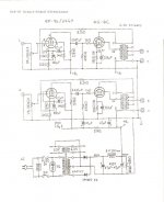
The circuit is a variation of JC Morrison's design here: http://tinpan.fortunecity.com/saints/668/primer/6l6-se.gif. My valve complement is a 5B/255M (an 807 variant) driven by 6SJ7. Also as my OPT doesn't have a UL tap I'm feeding the screen from a 250V Zener string from the HT tap on the OPT. Screen and cathode voltages on the o/p valve measure OK.
Problem started when I tried to measure the voltage at the anode of the 'SJ7. Almost immediately there were sparks followed by small fire at the anode pin of the 255M valveholder. I switched off at once and tried again to measure the same voltage but this time on the 'SJ7 of the other channel. Same result only this time with more spectacular (!!) pyrotechnics inside the o/p valve.
The problem seems to be on one channel only and linked to the OPT transformer. BTW I always test the amplifier with the speakers connected to the OPT secondaries.
What do you think? -- Thanks!!
Hi again, this is proving to be my most frustrating project, tho' I've learned a few things - leaky capacitors and gassy tubes - TNX a lot burnedfingers and 'foxy' Miles Prower.
The circuit is a variation of JC Morrison's design here: http://tinpan.fortunecity.com/saints/668/primer/6l6-se.gif. My valve complement is a 5B/255M (an 807 variant) driven by 6SJ7. Also as my OPT doesn't have a UL tap I'm feeding the screen from a 250V Zener string from the HT tap on the OPT. Screen and cathode voltages on the o/p valve measure OK.
Problem started when I tried to measure the voltage at the anode of the 'SJ7. Almost immediately there were sparks followed by small fire at the anode pin of the 255M valveholder. I switched off at once and tried again to measure the same voltage but this time on the 'SJ7 of the other channel. Same result only this time with more spectacular (!!) pyrotechnics inside the o/p valve.
The problem seems to be on one channel only and linked to the OPT transformer. BTW I always test the amplifier with the speakers connected to the OPT secondaries.
What do you think? -- Thanks!!
^^^^
Would you have another site for the schemo? That link leads to one of those gawdawful Fortune City sites where I get a "page not found", and thier search feature is utterly useless.
Would you have another site for the schemo? That link leads to one of those gawdawful Fortune City sites where I get a "page not found", and thier search feature is utterly useless.
Re: Fireworks on the anode of the OP valve!!
Without an actual schemo, it's hard to say. If the plate of the 6SJ7 is direct coupled to the grid of the final, and you accidentally had the DMM set for current instead of voltage you'd short out the plate and grid at the same time. I wouldn't expect a problem there since the final should go into cutoff. You might poof a meter and/or a 6SJ7 plate resistor, but that's about all. Worst case scenario would be poofing the 6SJ7 by removing its plate voltage with screen voltage still applied, which would burn out the screen. If capacitor coupled, I'd expect a momentary pop as the coupling capacitor discharged.
The whole problem still looks like a severe overvoltage caused by an inductive flyback. I wonder if the speeks were really connected? Given the impromptu light show you describe, I'd expect to hear some protests from the speeks. You didn't mention anything like that. Binding posts can fail and leave an open secondary.
sonata149 said:Problem started when I tried to measure the voltage at the anode of the 'SJ7. Almost immediately there were sparks followed by small fire at the anode pin of the 255M valveholder. I switched off at once and tried again to measure the same voltage but this time on the 'SJ7 of the other channel. Same result only this time with more spectacular (!!) pyrotechnics inside the o/p valve.
The problem seems to be on one channel only and linked to the OPT transformer. BTW I always test the amplifier with the speakers connected to the OPT secondaries.
What do you think? -- Thanks!!
Without an actual schemo, it's hard to say. If the plate of the 6SJ7 is direct coupled to the grid of the final, and you accidentally had the DMM set for current instead of voltage you'd short out the plate and grid at the same time. I wouldn't expect a problem there since the final should go into cutoff. You might poof a meter and/or a 6SJ7 plate resistor, but that's about all. Worst case scenario would be poofing the 6SJ7 by removing its plate voltage with screen voltage still applied, which would burn out the screen. If capacitor coupled, I'd expect a momentary pop as the coupling capacitor discharged.
The whole problem still looks like a severe overvoltage caused by an inductive flyback. I wonder if the speeks were really connected? Given the impromptu light show you describe, I'd expect to hear some protests from the speeks. You didn't mention anything like that. Binding posts can fail and leave an open secondary.
Thanks a lot Miles for your support. The actual schemo differs from the one posted in the following aspects:
1) Apart from the valve changes (5B/255M instead of6L6 and 6SJ7 instead of the EF86), the voltages and component values are practically the same.
2) My OPTs don't have a UL tap so I connected the screen to a 250V Zener string connected to the HT point on the OPT thru a 10K resistor.
Regarding your suspicion about the speakers, I will check again and report.
Miles wrote;
"The whole problem still looks like a severe overvoltage caused by an inductive flyback."
Checked resistance at OPT's points. Secondaries - 6.9K; Primaries - 96.4 ohms. Now I always thought that OPT secondary is always lower than primary. The transformer is spec'ed at 2.5K primary and 0-4-8 ohms.
If I swap the connections where does the HT go, to the 8 ohm or 0 point?
sonata149 said:Checked resistance at OPT's points. Secondaries - 6.9K; Primaries - 96.4 ohms. Now I always thought that OPT secondary is always lower than primary. The transformer is spec'ed at 2.5K primary and 0-4-8 ohms.
That isn't right. Somehow you've switched the primary and secondary. I've heard that some Hammonds were mismarked like that.
If I swap the connections where does the HT go, to the 8 ohm or 0 point?
I don't think it makes much difference. Just make the connection so's your gNFB is phased correctly: for negative feedback, not positive.
Thanks Miles Prower and all who have offered their help. I changed the connections but this time I'm getting the wrong voltage readings (with a DVM).
HT has shot up to 418V (previously - with the transformer's original taps it was around 360V) and screen voltage is well below the 250V mark - around 70 - 80V. I couldn't make any more checks because soon the 10K dropper resistor from HT to the Zeners started frying (!) and I had to switch off. Seems like it was passing the full plate current not just the screen's. This happened 4 or 5 times before on both modes of trfx connections.
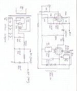
I'm attaching my own sketch of the circuit which is a sort of hybrid between 2 circuits - the o/p stage from Triode Dicks's site 807 PentodeSE and the driver stage is an adaptation of the Fi Primer (JC Morrison's site) 6LS UL SE. I hope it gives a better clue as to what I could be doing wrong.
HT has shot up to 418V (previously - with the transformer's original taps it was around 360V) and screen voltage is well below the 250V mark - around 70 - 80V. I couldn't make any more checks because soon the 10K dropper resistor from HT to the Zeners started frying (!) and I had to switch off. Seems like it was passing the full plate current not just the screen's. This happened 4 or 5 times before on both modes of trfx connections.
I'm attaching my own sketch of the circuit which is a sort of hybrid between 2 circuits - the o/p stage from Triode Dicks's site 807 PentodeSE and the driver stage is an adaptation of the Fi Primer (JC Morrison's site) 6LS UL SE. I hope it gives a better clue as to what I could be doing wrong.
Attachments
Joe,
I use 807s, too. I recommend to load the secondary with a dummy load, in order to save your speakers. Then put a resistor (47R to 470R) series with g2, that prevents HF oscillation. The 10k resistor that sets the zener current should be at least 5W. Also g2 draws some current through this resistor.
I would check the OPT, too. Find the primary and secondary (primary has higher resistance, thinner wire). A good check is to connect the primary to the mains 230V (secondary open) and measure the voltage at the secondary. Be very careful, think twice what you are doing!
If the transformer is OK, you can try connecting g2 (through the 470R resistor) to the anode. It won't harm the tube, I run mines in this triode-connected mode for years. The current/voltage in my circuit is -35V/50mA at 415V plate voltage.
Laszlo
Hey Laszlo, I did the AC check on the OPT, did some ratio calculations and I found what was wrong. There was supposed to be a link on the sec which was omitted. TNX a lot for the tip. Now I understand what Miles Prower was saying all the way about 'inductive flyback' from the OPT !!
Laszlo, I also connected g2 via a 470R resistor but I'm not sure which I prefer, whether this connection or the 250V zener supply. So I'll make it switchable.
How do you know when to adjust the current thru the o/p valve? Is it because you get a high voltage at the cathode? Do you then adjust the cathode biasing resistor according to the current you want to pass thru the valve?
Thanks and regards to all.
Joe A
Joe,
I am happy that I could help. I use fixed bias and measure the voltage drop on a small resistor in the cathode. In your circuit you can measure the voltage drop directly on the cathode resistor. Try to keep the current in the 30-60 mA range, altough there is not much setting possible in an autobias circuit, apart from replacing the failed tube.
Laszlo
oshifis said:Joe,
I use 807s, too. I recommend to load the secondary with a dummy load, in order to save your speakers. Then put a resistor (47R to 470R) series with g2, that prevents HF oscillation. The 10k resistor that sets the zener current should be at least 5W. Also g2 draws some current through this resistor.
I would check the OPT, too. Find the primary and secondary (primary has higher resistance, thinner wire). A good check is to connect the primary to the mains 230V (secondary open) and measure the voltage at the secondary. Be very careful, think twice what you are doing!
If the transformer is OK, you can try connecting g2 (through the 470R resistor) to the anode. It won't harm the tube, I run mines in this triode-connected mode for years. The current/voltage in my circuit is -35V/50mA at 415V plate voltage.
Laszlo
To set the current through the tube with 'cathode-bias' you'll need to alter the value of the cathode-resistor. A higher value will reduce the current, as the voltage developed across the cathode-resistor is used as the 'neg' bias for the grid, ie, the Cathode is more Positive to the grid, while the grid is close to or at 0 volts....
Or to put it another way, the Grid is more Negative to the Cathode, by the amount of Positive voltage at the cathode with respect to '0' volts...
330 ohm looks quite reasonable for the 807/6l6 types, if one of your tubes is still giving a big difference to the other, I would suspect that tube of being faulty. There is usually only a volt or so diference between Unmatched tubes at the cathode.
A good way to check the actual Anode-current is by adding a 10 ohm resistor in the anode lead to to trans. and attaching a voltmeter across the resistor. Take care, the meter and leads will be at full +B voltage, Attach before you turn on the jiuce, and switch off before you disconnect, just to be safe!
- Status
- Not open for further replies.
- Home
- Amplifiers
- Tubes / Valves
- Help - 807 Technical problem