Update on the build, it has some sound coming out but its not working correctly.
When i connect the 12at7 the B+ from the power supply drops 140V, from 290 to 150v. Though if i only connect the power tubes it drops only 8/10v.
I tried with 4 different tubes, 3 used one new. The amount voltage drop differs between them but at this point i suspect they are not the issue.
What could cause this?
I get some low volume sound coming out but maybe 0.5W max and highly distorted
Hi, I don't have a photo of the actual amp on me but i'll provide schematics and I'll take an actual picture when I get home.
I used diylc to make a turret board layout, i think what i did is correct as i looked at all the nodes where components connect but it did take me some time to wrap my head around it.
Differences compared to the original schematic i had posted:
Power supply:
since i had more than 300something B+, made a voltage divider with a 56k resistor and i get B+ 287VDC
Audio Signal:
after the 100k pot i used 220ohm resistor since i didn’t have a 200ohm one. I figured it would make a minimal difference, maybe just attenuate it a bit (correct me if im wrong)
12at7 cathode bypass:
The original plan doesn’t have one, the schematic provided by @dubadub has one so i figured it shouldn’t cause issues, only change frequency response (again correct me if wrong)
A friend suggested to check the preamp cathode resistor as he thinks it is drawing too much current
I’ll measure the voltage again but I think it was 0.8v on a 499ohm resistor so 1.6mA (?)
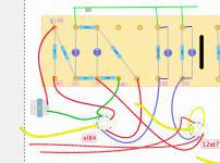
I used a turret board, I’m almost certain I did the connections correctly but ill attach a drawing of it.
I used diylc to make a turret board layout, i think what i did is correct as i looked at all the nodes where components connect but it did take me some time to wrap my head around it.
Differences compared to the original schematic i had posted:
Power supply:
since i had more than 300something B+, made a voltage divider with a 56k resistor and i get B+ 287VDC
Audio Signal:
after the 100k pot i used 220ohm resistor since i didn’t have a 200ohm one. I figured it would make a minimal difference, maybe just attenuate it a bit (correct me if im wrong)
12at7 cathode bypass:
The original plan doesn’t have one, the schematic provided by @dubadub has one so i figured it shouldn’t cause issues, only change frequency response (again correct me if wrong)
A friend suggested to check the preamp cathode resistor as he thinks it is drawing too much current
I’ll measure the voltage again but I think it was 0.8v on a 499ohm resistor so 1.6mA (?)
I used a turret board, I’m almost certain I did the connections correctly but ill attach a drawing of it.
Attachments
500R cathode resistors on the preamp tube seems a bit small, I'd expect 1K2-1K5.
And I'm not sure that power supply is gonna work. The voltage divider at the front might change behavior as the output stage draws more current. More common to see a dropping resistor in series with the filter caps to achieve an ideal voltage range, and control the current thru the tube via the cathode resistor.
And I'm not sure that power supply is gonna work. The voltage divider at the front might change behavior as the output stage draws more current. More common to see a dropping resistor in series with the filter caps to achieve an ideal voltage range, and control the current thru the tube via the cathode resistor.

Why do you use AC blocked cathode resistor in first stage?.. but i'll provide schematics ...
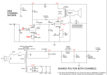
This is the last version of RH84
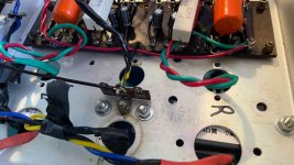
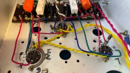
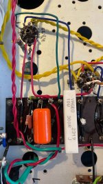
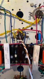
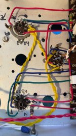
Ok so I've attached the pictures of the actual wiring.
@dubadub not sure voltage divider is the correct definition... I added a 56k resistor in series after the filter caps, and since there already was a 220k bleeder resistor I guess it forms a voltage divider. Is what I did correct? Is it the proper way to drop 75V? Sould I use a 75v Zener instead?

I'll see what happens increasing the cathode resistor.
One thing I noticed by looking at 3 similar schematics is that the ratio between anode to cathode resistor value is approximately 100x. (yours 100k/1.2k , rh84 22k/240r , the one i followed 47k/499r) So will changing the cathode resistor also require adapting the one on the anode?
@euro21 I added a bypass cap because dubadub has it set up like that way his schematic. What issues can this cause?
@dubadub not sure voltage divider is the correct definition... I added a 56k resistor in series after the filter caps, and since there already was a 220k bleeder resistor I guess it forms a voltage divider. Is what I did correct? Is it the proper way to drop 75V? Sould I use a 75v Zener instead?
I'll see what happens increasing the cathode resistor.
One thing I noticed by looking at 3 similar schematics is that the ratio between anode to cathode resistor value is approximately 100x. (yours 100k/1.2k , rh84 22k/240r , the one i followed 47k/499r) So will changing the cathode resistor also require adapting the one on the anode?
@euro21 I added a bypass cap because dubadub has it set up like that way his schematic. What issues can this cause?
Attachments

The series resistor may be 56K for no load, but will need to less than 1K with 80 mA though it - and the choke will drop 20V, Maybe 470 Ohms, and it will need to be 10 watts - 5W is marginal. Put it in series with the choke,100 uF filter cap after that. If you have any power resistors, you try series or parallel combinations until the voltage comes out right. If not, use PSU Designer and buy the resistor that gives the right output voltage. You'll need to measure primary and secondary DC resistance of the power transformer - you have the other circuit values you need.
1.) As @Tom Bavis wrote, try to measure PT parameters (and load current) to design any PSU.
This is the sample of specified PT transformer (Indel TSL 100/001) and 2x 37mA load PSU:

As you can see, at the full load (74mA), the voltage on first capacitor and desired output voltage difference and load current determined the R1 value.
BTW the simple CRC filtering IMO not sufficient for SE amplifier, the hum value (in this case 110mVpp) too large.
If the financial opportunity are limited, or choke can't fit, another R-C stage may become necessary to decrease B+ hum.
2.) @dubadub built EL84 SE, you want RH84 variant. These are different designs, with such little practice that you have, it's not worth taking parts between its. Build one or the other.
3.) The OPT determines the power amplifier behaviour at least 50 percent. Without OPT parameters not possible designing tube amplifier (with transformer).
This is the sample of specified PT transformer (Indel TSL 100/001) and 2x 37mA load PSU:
As you can see, at the full load (74mA), the voltage on first capacitor and desired output voltage difference and load current determined the R1 value.
BTW the simple CRC filtering IMO not sufficient for SE amplifier, the hum value (in this case 110mVpp) too large.
If the financial opportunity are limited, or choke can't fit, another R-C stage may become necessary to decrease B+ hum.
2.) @dubadub built EL84 SE, you want RH84 variant. These are different designs, with such little practice that you have, it's not worth taking parts between its. Build one or the other.
3.) The OPT determines the power amplifier behaviour at least 50 percent. Without OPT parameters not possible designing tube amplifier (with transformer).
Thanks to both. @euro21 I appreciate you taking the time to go into such detail.
1) I swapped the choke for a 270ohm 10w resistor due to price reasons, happy to add another RC stage but I guess hum is a secondary issue if I can't get the rest working in the first place.
2) What I tried to build was the EL84 SE as those are the component values i used (once I remove the cathode capacitor on the preamp).
The reason is that RH84 has tube rectifier and the LM317 to bias the tube and I figured that automatic bias would be simpler to understand and change if needed, as well as a cheaper power supply.
What I don't understand is why does my DC measure 368V instead of the 290V written in the schematic, even though the PT is outputting only 20V more? Is it because the B+ of the schematic considers it with the tubes inserted and therefore also the voltage drop I experience when it sees the load of the 12at7?
3) Regarding OPT I bought the cheapest chinese ones i could find, I know they probably won't make a good amp but it's more for a proof of concept to play around before spending more money. I already built a cheap SET kit that had the same OPT's and 6n2+6p15 tubes and it sounds satisfying enough for what I paid, so what would stop them from being suitable in this design?
If you can measure PT and OPT DCR values, I will design for you in simulator the PSU and the amplifier.
The amplifier circuit has nothing to do with the power supply circuit. The power supply just has to have the correct voltage and low enough ripple. With plate-to-plate feedback, the driver cathode should not be bypassed - this will reduce gain, but also distortion.
Adding another R-C section may make up for the missing choke - it's actually a good thing if the transformer voltage is too high. The total current with one channel will be about 40 mA, 80 mA for two. And the total resistance needed will be V/A - desired voltage drop divided by current in amps - i.e. 0.040 for 40 mA.
Adding another R-C section may make up for the missing choke - it's actually a good thing if the transformer voltage is too high. The total current with one channel will be about 40 mA, 80 mA for two. And the total resistance needed will be V/A - desired voltage drop divided by current in amps - i.e. 0.040 for 40 mA.
- Home
- Amplifiers
- Tubes / Valves
- HELP 2nd amp build: Adapting a schematic to the components i already have