lol!
Just wait until you clean up a design using a quad op amp!
When we design, we use the symbols. After we decide which goes in which package and what kind of packages (single, dual, quad) for the PCB layout. Placing the symbol logically in the circuit makes it much easier to get your head wrapped around it. Others can follow more easily.
For learning, I imagine drawing the guts of the op-amp might help? Maybe excessive, but i'm getting along much better with splitting them up in two.
I am curious is it ok to flip the components and or change the pin labels if I'm just making the drawing not making a PCB?
Well, components at the silicon level are a little different than parts you and I can grab. If you draw it out it may help, but there are special things they can do with the close parts matching in silicon, and odd multi-electrode connections we do not have parts we can hold and use. It may help your understanding. There are concepts and knowledge far beyond what you normally learn in university or college. Don't attempt to break an op amp down in a normal schematic though!
You can use different pin numbers, but I don't see any advantage. It would confuse you or someone else when troubleshooting. These are just labels, so there is no point in changing them. In short, I wouldn't.
You can use different pin numbers, but I don't see any advantage. It would confuse you or someone else when troubleshooting. These are just labels, so there is no point in changing them. In short, I wouldn't.
Thanks anatech, just so you know, you are my go to guy on this project. So helpful! Last night I got a much better draft that I will now correct from the board traces to find my mistakes... I also looked over my notes of measurements and I saw R40 and R41 returned OL. Which I expected because they share a pad with that large electrolytic. My initial drawing of the transformer and rectifier are not in EDA yet since the distortion is my focus. The power supply would make a worthwhile addition. Incidentally I started to wonder just how many old pieces of electronics are being lost every year. Like this one which sounds quite nice but seems to be completely undocumented. Bet you've run across that before? Anyway, here's the latest, feels lots clearer to me at least.
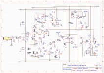

Thanks, others can help just as much.
Okay, so the cold end normally is returned to signal common (ground) on C6 / volume. The distortion signal goes somewhere (Q3 circuit). The speaker gets a push-pull signal and has to sit at common potential. If you only have a +45 VDC high current supply, the speaker must go through a capacitor and the circuit side would sit just under 22.5 VDC. Normally ou would see a plus and minus supply, but not always. British designs retained the single supply / coupling capacitor design much longer than everyone else.
R40 and R41 might be fuses or low value resistors. Hard to say since the output power stage has drawing problems. Try to retrace it assuming nothing, don't even look at your previous work. It might help to look at single supply output stages in other equipment, and also bipolar. Confirm if you have a single power supply, or a bipolar (with plus and minus) going to the output stage.
Good call, I'll review the output and add the power supply to the drawing over the weekend.
Separately I did a thermal scan and was surprised there was a lot of heat in a few spots... Well not really surprised, more intrigued. The hottest ones are the 820ohm resistors not in the schematic. So having that in the drawing will help me understand it.
R17 is only included since it was blown, replaced, and may be useful to note? I assume It blew because C31 had come loose from the board sometime during this amps ebay history.
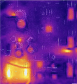
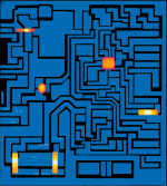
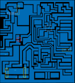


Last edited:
hey! don't know if you fixed this already but noticed this ...Thanks anatech, just so you know, you are my go to guy on this project. So helpful! Last night I got a much better draft that I will now correct from the board traces to find my mistakes... I also looked over my notes of measurements and I saw R40 and R41 returned OL. Which I expected because they share a pad with that large electrolytic. My initial drawing of the transformer and rectifier are not in EDA yet since the distortion is my focus. The power supply would make a worthwhile addition. Incidentally I started to wonder just how many old pieces of electronics are being lost every year. Like this one which sounds quite nice but seems to be completely undocumented. Bet you've run across that before? Anyway, here's the latest, feels lots clearer to me at least.
View attachment 1392811
Thanks drinkingcube, I did see that, seems rotating designs in easyEDA occasionally breaks stuff. I fixed it but not everything, lol. Appreciate extra eyes on this project!
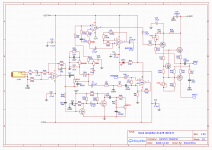
Hope everyone is merrily preparing for the holiday. I've done a rework of the schematic and welcome your input. Each pass I make over the board I seem to find something missing or connected wrong, so please be kind. It is a far way from being done, but wanted to share what I have so far. My focus this pass was to look hard at the output. The last thing I caught was that the largest capacitor C31 goes from ground to 46V from the transformer. Does that stabilize the circuit somehow?

Last edited:
Hi roxteek,
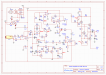
Much better, still some problems in the output stage with the drawing (or just the way it is drawn). Look at other examples of a single supply output stage for guidance. Those 10R resistors on the output emitters are probably much lower in value (or should be).
C31 give a low AC impedance to ground for the supply. That might even be your main filter capacitor from the rectifiers.
Thanks anatech, sure am glad it's making more sense. I added the power stage and the schottky diodes. I think you're right that C31 is the main filter cap. And looking at several single supply output circuits, they all seem to have a symmetry mine lacks. I'll try and find the symmetry somehow. As It takes shape I am noticing the blocking capacitors need to have their direction checked too. What is weird to me is that having split the op-amps I've now got duplicate power on pins 8 and 4. Is there a better way to represent that?

Last edited:
- Home
- Amplifiers
- Solid State
- Hello from Illinois: I'm Restoring distortion in an Rock Amp