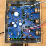
A christian outfit called Rock Amps out of Pomona CA apparently made a number of SS amps. Mine is from 1978 and unlabeled except for a sharpie SN inside the case and a Stonebridge Music Store Logo from Garden Grove CA. Haven't found a schematic online so I'm working on that. It uses two UA1458TC's, has treble, bass, reverb(spring tank), and a distortion knob. The distortion does very little but the circuit looks like a fuzz, maybe? The large cap on the trace side had come loose and the 20 Ohm resistor was blown. I'm starting to make a schematic to troubleshoot the lack of any significant change when turning the distortion pot. I figure the large cap coming loose whas what caused the resistor to blow, but like I say I'm just starting on this one, identifying components and following traces to get a schematic. Thanks for any input folks!!
Attachments
Thanks for letting me join. I grew up in the hills of southern Indiana but have spent my adult life in Chicago. I wear a lot of hats, I've done computer engineering work for Ad companies, sold a fair number of my paintings, built a few houses, and recently rekindling my love of music gear. Last year I restored a friend's Dwarf and cloned the circuit board, repaired a Gibson Skylark, and rebuilt a 70's Big Muff. I may buy an ossiliscope if I can get a little further along in my electrical deep dive.

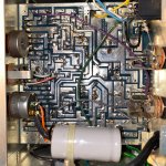
I've made progress mapping traces. I started in the upper right working from the pot labeled "Distortion." I thought it would trace back to the blown 20Ohm resistor (yellow box upper left) but nope. Honestly I need to do more toward making a full schematic. But this is the most complex circuit I have worked on.
Attachments
So, working on the schematic I cant identify this orange drop or find a match in easyEDA. Any ideas? 
Thanks huggygood, I looked over that in my initial search results but I didn't see any 4 digit code that start with a decimal place? My only take away from the link is that the k=10% tolerance. But hey, you were the only person who responded so, much appreciated. I created a place holder in the schematic until I get more info. What stands out is that there are only 3 orange ceramic caps, each one in a stage connected to the op-amps. This one separates the Distortion pot wiper and 0V or ground.
The next parts to document are the two black blocks circled in blue by the fets. I think they are resistors? they go from emitters to a big electrolytic cap>0V.
If anyone recognizes this type of distortion stage, let me know, Thanks.


The next parts to document are the two black blocks circled in blue by the fets. I think they are resistors? they go from emitters to a big electrolytic cap>0V.
If anyone recognizes this type of distortion stage, let me know, Thanks.
It’s been a bit since I posted, and I’m still struggling with identifying a couple of components and fixing the distortion circuit in this Rock Amplification A1278. Any fresh insights would be greatly appreciated! Im attaching the schematic I have so far.
note: a link to my other post asking for assistance at TDRi here: https://www.tdpri.com/threads/help-...k-amplification-a1278-1978-pomona-ca.1165270/
note: a link to my other post asking for assistance at TDRi here: https://www.tdpri.com/threads/help-...k-amplification-a1278-1978-pomona-ca.1165270/
Attachments
Hi roxteek,
To do anything close to a halfway competent job on anything you need a couple instruments. If you repair anything, you need a good DVM, a decent scope (analogue dual trace would be my recommendation) and audio oscillator. This is a bare minimum! You also need to understand how the stuff and equipment works. A controlled temperature soldering station (not just an iron). Do not repair anything for anyone else!!! Not until you are competent.
This stuff may look easy, and you can get something making noise while it isn't even close to working properly. You need to repair it right, not hack it. Professional techs hate, hate, hate cleaning up afterwards.
Please, no shortcuts. Learn something first. Look at my signature line and think on it, please.
We are happy to help, but no one can be the brain operating a pair of hands long distance. It doesn't work well.
So, working on the schematic I cant identify this orange drop or find a match in easyEDA.
Not so easy, many times you will have to make your own footprint.
That .0022k is the capacitance value, which is 2200pF.
Fortunately rayma, this old board was laid out for multiple applications or versions in mind and several components share the same footprint. Very forward thinking on the part of the designer. I saw one photo of the same board sparsely populated in an amp without reverb or distortion.
Thanks anatech, for the tool recommendations, I’m covered except the scope which would be fantastic but out of reach unless you know of an inexpensive one?
Also, rest assured I’m not hanging out a shingle or doing this as a business. It’s a hobby and I’m seeking feedback on best practices for drawing a schematic from those more expert with keen eyes for components, and circuit conventions. Most parts are identified with the exception of R40 and R41, I place marked in the drawing as 10 ohm resistors, could they be relays? I hadn’t planed to desolder anything if I can find an expert opinion. Care to speculate? Of course if you’re interested and willing you can always stay at my house and We'll make short work of it.
Also, rest assured I’m not hanging out a shingle or doing this as a business. It’s a hobby and I’m seeking feedback on best practices for drawing a schematic from those more expert with keen eyes for components, and circuit conventions. Most parts are identified with the exception of R40 and R41, I place marked in the drawing as 10 ohm resistors, could they be relays? I hadn’t planed to desolder anything if I can find an expert opinion. Care to speculate? Of course if you’re interested and willing you can always stay at my house and We'll make short work of it.
Last edited:
Hi roxteek,
No problem. I'm all for learning, but you can't learn much by taking big bites.
I'm really glad you have some equipment. For an oscilloscope, try Tek 2235 scopes, or Philips PM3070 or related. Those are very good. A budget B&K or Leader (better) also works well. I have had many pretty good analogue scopes and fitted out a large service shop with various oscilloscopes. The basics, make sure the screen isn't burned or dim and is sharp and clear. I am absolutely unimpressed with my Tek 2465B, fuzzy trace. Slow. Don't go for features, a good basic scope is exactly what you want. The better scopes have lower noise and higher sensitivity. 100 MHz dual trace should be good for a long time as far as what you need.
Digital scopes generally don't perform well for their core function. Their toys are sometimes cool, but you really want to see the trace clearly at the end of the day.
Tracing a circuit takes patience and experience. Knowing how the circuit should look is a massive help. Spend time learning the basics and component designations. Don't believe everything you read/see on the internet. Building some well documented kits would help as well. They don't have to be big. Too bad Heathkit isn't around anymore.
Hi all, I’ve updated my schematic with a more standard layout—I had to rotate parts and so I still have to get the ground to aim down. but the input is now on the left, output on the right, and trying to get the power rails horizontal. I’ve also grouped by stages, which I think correspond to the 5 control potentiometers. It’s still a work in progress, but it’s coming together!
I’m particularly curious about R40 and R41, which I’ve marked as 10Ω resistors, could they be relays, or am I way off? Also, feedback on the stage grouping and general layout would be much appreciated. Here’s the latest version:

I’m particularly curious about R40 and R41, which I’ve marked as 10Ω resistors, could they be relays, or am I way off? Also, feedback on the stage grouping and general layout would be much appreciated. Here’s the latest version:
Hi anatech, Thanks for the scope recommendations! There are several Teks and Philips on eBay in the 75-400 dollar range, condition is a crapshoot though. I could get one for $60, but then I'd be asking how to fix that, lol... I hear you about analog clarity. There’s something satisfying about simplicity and precision over features I don't expect to need as a hobbyist.
I also really appreciate the perspective on tracing circuits and learning by doing. The amp works but I want to understand the circuits better, and hearing from someone with real experience is invaluable. That said, the puzzle of R40 and R41 still has me scratching my head. I’ve marked them as 10-ohm resistors in my schematic draft, but could they be something else, like relays? I'd love to hear your take before I start poking around more~ it’s all part of piecing this together! I really enjoy this kind of hands-on learning. Thank you for sharing your time and insights!
I also really appreciate the perspective on tracing circuits and learning by doing. The amp works but I want to understand the circuits better, and hearing from someone with real experience is invaluable. That said, the puzzle of R40 and R41 still has me scratching my head. I’ve marked them as 10-ohm resistors in my schematic draft, but could they be something else, like relays? I'd love to hear your take before I start poking around more~ it’s all part of piecing this together! I really enjoy this kind of hands-on learning. Thank you for sharing your time and insights!
Our posts just crossed paths. Got it about the relays idea, I didn't think they were, but I have not seen that form factor so was guessing, thanks. When you say. "Flip section DIST1 so it's easier for others to follow." do you mean flip vertically? those op-amps are tough to orient with ins and outs on both sides. Its draw and redraw but I hope to get there. I'll have another crack at it.
Hi roxteek,
As for your equipment ... you cannot afford to fight your equipment. Some will lie to you under various conditions. Digital scopes can really mislead you. Digital voltmeters are another instrument that can lie to you - big time! Try to read the accuracy specs and understand them. With cheap meters, 3 1/2 digit, that last digit is pure fiction. Learn to say "about this much" instead of rhyming off the digits. Many don't go that high in frequency with any accuracy either. We're talking 400 Hz as pushing it. There are very good reasons why $400 ~ $700 Fluke and Keysight meters exist. The better meters hold their calibration, the cheap ones drift out and normally aren't even in tolerance when brand new. Good bench meters are even better, 0.05% basic DC accuracy, AC up to 300 KHz for example. Those are expensive meters. Don't look at how many digits a meter has, read the specs. No comprehensive specifications? Pass on it. Look at really good meters and their spec sheets first, then look at cheaper ones. At the minimum, have realistic expectations for your equipment.
Look at those parts. Do they look like resistors (mostly two terminal, cylinders) or a box with at least 4 terminals, probably more? In those positions they would make more sense as resistors. Have you measured them?
Most circuits read more easily with common (ground) at the bottom, if the circuit has both plus and minus polarities, the negative one should be the lowest. The common potential would then be through the middle in most cases, or lower. Just look at some good schematics. Older drawings most often follow convention. Start with tube circuits just to see. This carries over as convention.
If you look at the schematic of a package (8-pin DIP) in the data sheet, they show a triangle with the leads labeled, copy it but ignore the box. Just show them as say Q4a and Q4b You will find it much easier to understand.
Excellent, those monoliths (as I call them) each have two terminals and pass from the 45 volt rail of the power supply to transistors. I'll post the measurements. Should I do that while it is running? In the drawing I was trying to reformat with rails top bottom and middle. The software is trickey, when I move things around the wiring goes all wrong. so it may take some time or require a fresh start. Thanks you, thank you!


Last edited:
They could be fuses. Can you post clear pictures of them, not just from the top. An angle would help.
Nothing like having the unit in front of you on the bench.
Nothing like having the unit in front of you on the bench.
- Home
- Amplifiers
- Solid State
- Hello from Illinois: I'm Restoring distortion in an Rock Amp