I've been a member for a few days now... ...it's really nice to find a group of people interested in DIY projects...
I play with high power audio, and build a lot of Switching power supplies for fun. (Any one interested in car audio power supplies, let me know)
By trade I'm a design engineer. My hobby... well, er... ...my wife would say it's buying test equipment, but I love electronics and science.
Current projects are a 4Ch 450W/Channel mosfet Amp, and a 12 to +-65VDC 2KW power supply to run it in my truck... ...all working, just need to be packaged, and a few small tweaks. The designs are from scratch. One future project is a computer interfaced curve tracer/burn in unit to test and match transistors.
My amp's power bandwidth is from DC to 40K (-3dB). Uniform gain from no load to 2Ohm load. It sounds really good, and I've had a hard time finding quaity recordings to listen to, and am currently unimpressed with most commerically overproduced music, yuk!
To date the best I've found is a set of pro test CD's.
Anyway, enough rambling... ....feedback welcome!
-Dan
2KW from 12V 166 amps in- That's amazing. I would like to see some schematics on that. We really could use a few more people who actively design things here.
Darrell Harmon
Darrell Harmon
2KW from 12V...
Yeah, it is alot of current. I'm assuming about 80% eff. Also, my supply rail dropped to 9v at full load, so it was more like 275 amps input. 275 amps is close to what my hall effect current probe was reading. For dummy loads, I use twenty 100W incadescent bulbs. They make a great dummy load for 130V!
Supply is the same as any other push pull 12V supply (Look at any modern car audio amp). Basically a center tapped transformer, with each leg switched to ground alternatley (Center to +12V). The secondary, (Actually to of them, in series to give the +- Rails) are half wave rectified and filtered with a small ammount of inductance and about 16000uF of panasonic caps per rail.
I'm planning on some improvements to the amp, and then want to get some other people to build some, maybe then a kit, if I can find some $$$ backing...
I'll see if I can borrow a digital camera to get some pics on the web! The supply looks really mean... ...like something out of a SCI-FI movie.
-Dan
Re: 2KW from 12V...
What exactly are you using to switch it to ground? I'm guessing parallel fets?
I once built a supply like that, but not as big. I used a ferrite transformer and it put out about 3KV into no load. I would definitely be interested in some schematics for the ps.
Darrell Harmon
dkemppai said:
Basically a center tapped transformer, with each leg switched to ground alternatley (Center to +12V).
-Dan
What exactly are you using to switch it to ground? I'm guessing parallel fets?
I once built a supply like that, but not as big. I used a ferrite transformer and it put out about 3KV into no load. I would definitely be interested in some schematics for the ps.
Darrell Harmon
Darrell,
Yes, parallel fets is exactly what I'm using. I did some cost/switch time/current/RDS on comparisons of about 10 of IRF's fets a while back. I turned out that paralleling IRF1010N's was the best way to go. I run 6 in parallel, with 1/16th inch by 3/8 Inch coper buss bars to them. The buss bars are soldered onto a circuit board, and there is one for every 3 fets. They run at about 40Khz.
I did put a a couple of 45 Volt TVS's across the switches, just in case transients go high once in a while, although I've never seem them work, even at high loads.
Actually, transistors are the easy part, there are a lot of them out there that will work just fine. The hard part is the physical layout, with cooling and inductance being major concerns. Some of it is just having a good scope to see what's going on. Once you get the hang of it, there's really nothing to it. (Again, having a good scope really helps)
-Dan
Hello All
Hi, I'm Joe
I have been a member here for a few days also and I thought I had better make an introduction of my own. I'm just a crazed audio nut for 30+ yrs. I'm not an engineer by any means. I am employed by a sound contractor and I fix what others brake. I am at home with any system from 5 watts to 50,000 watts. In my spare time I work,think, and play audio. I have recently been bit by the "Tube Bug" and I must admit my experience lies in the SS field. I hope that in addition to learning that maybe I can contribute something here also.
cowanrg said:wow, sounds like you are gonna be a great resource for us! post any pics you have of your stuff.
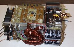
Finally, some pics for all to see!
This is a pic of my SMPS supply. Keep in mind that some of the wires need to be shortened, and routed. Also the filter inductors need to be mounted...
Attachments
- Status
- Not open for further replies.
- Home
- Member Areas
- Introductions
- Hello all...