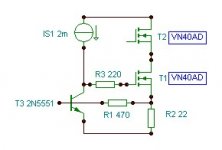
Those two MOSFETs form a Single Ended Class A buffer (upper is a Source Follower, the lower one is CCS running on about 25mA of Id).
If I were you I'd not lose my sleep over VN40 (nothing really special about that part in that circuit). I'd rather make a nice buffer with better parts (2SK2013 comes to mind) which would surely be an improvement to your EQ.
Ok, so let's see if I've got this straight. The lower MOSFET is simply a CCS for the upper (supplying ~25mA), and the upper is a source follower whose purpose is to buffer the signal from the opamps, presenting the opamps with a high input impedance while presenting a low output impedance and adequate current to the following amplifier.
So, if I wanted to try out another MOSFET to see if I could improve the sound, could I simply replace the upper MOSFET with a substitute with somewhat similar characteristics (say a Toshiba 2SK2013 or Renesas 2SK213) and leave the lower CCS alone? I realize the pinouts for the lateral MOSFETs are different but that's simple to fix.
Magz, this you are after takes design skills. If you change to more modern types of mosfets you should be aware of different gm which has influence on the distortion (and distortion spectrum) and the output impedance. From what I read from datasheets the VN40 is pretty good for this task.
Well, what about this idea: For $10 I can try out two 2SK2013 MOSFETs in the circuit and see how they sound. If I don't like it, I can always just put the VN40s back in. I've always been much more of an experimentalist than a theorist, and there's no chance of destroying the equalizer by doing that, correct?
I don't know what other changes might need to be made to the circuit for your mosfet swap, but you might find that with the EQ in place in stock form is part of how infinity voiced the speaker system. It could be that despite being a LF EQ, it does shape the rest of the range. You may be moving it away from whatever frequency response curve they intended. Which is not to imply that you or I might not prefer it changed.
I've got the RSIIIa's (not really even similar), but I made a lot of changes to get them the way I like, so I applaud your efforts.
I've got the RSIIIa's (not really even similar), but I made a lot of changes to get them the way I like, so I applaud your efforts.
I don't know what other changes might need to be made to the circuit for your mosfet swap, but you might find that with the EQ in place in stock form is part of how infinity voiced the speaker system. It could be that despite being a LF EQ, it does shape the rest of the range. You may be moving it away from whatever frequency response curve they intended. Which is not to imply that you or I might not prefer it changed.
I've got the RSIIIa's (not really even similar), but I made a lot of changes to get them the way I like, so I applaud your efforts.
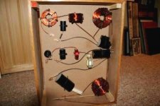
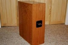
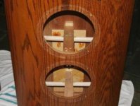
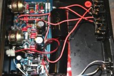
Too late for those concerns. I've already torn out the entire speaker crossover and built external ones (pictures#1&2), added bracing and sealed the speaker boxes (picture #3), replaced all the caps, resistors, opamps, wiring in the equalizer (picture#4), and am waiting for all new EMIM and EMIT diaphragms from Apogee. These speakers will not sound much like stock after all that, so the MOSFET swap doesn't worry me in that regard.
You're an AK'er, right? I'm Maxamillion over there.
Attachments
Last edited:
You're an AK'er, right? I'm Maxamillion over there.
Yep, same username there. I've added bracing and changed the crossovers, but mine don't have EMIM's or active EQ'ing. Probably just as well, one less thing for me to mess with.
Last edited:
A Zero Tempco of 300mA at a Vgs of 4V isn't that bad, sort of reminds me of the Superdupertex VN13**/VP13** series.
(even a used-to-be favored by some of the big boyz like CH)
Yes that's a nice property, but completely useless in this circuit - here it runs on 25mA...
....
So, if I wanted to try out another MOSFET to see if I could improve the sound, could I simply replace the upper MOSFET with a substitute with somewhat similar characteristics (say a Toshiba 2SK2013 or Renesas 2SK213) and leave the lower CCS alone? I realize the pinouts for the lateral MOSFETs are different but that's simple to fix.
To solve the problem at hand, it might be best to seek help from a skilled neighbor - in your case, neighbor's nick is jackinnj
I've ordered a few of the Toshiba 2SK2013 MOSFETs to try out. I'll report back once I get a chance to solder them in and have a listen. Since the VN40s were never intended for audio, but the 2SK2013s are, I'm hopeful that I see some benefits. As they say, nothing ventured, nothing gained.
Those two MOSFETs form a Single Ended Class A buffer (upper is a Source Follower, the lower one is CCS running on about 25mA of Id).
If I were you I'd not lose my sleep over VN40 (nothing really special about that part in that circuit). I'd rather make a nice buffer with better parts (2SK2013 comes to mind) which would surely be an improvement to your EQ.
So Juma, you have piqued my curiosity. Can you elaborate on the "nice buffer" you would build? I have four of the 2SK2013 on their way to me now. I was just going to swap two in for the source followers and see how that sounded, but I think you have something more in mind judging by your above quote.
As I have read up on source followers, it seems to me that they don't do very much that could affect the sound - seems like all the hard work is being done by the CCS in keeping the current constant. I have previously implemented a CCS in my 2C22 tube preamp (cascoded IXYS 10M45S) and it transformed the preamp! I was wondering if a better CCS in the equalizer might have more effect than a different follower - your thoughts?
...Can you elaborate on the "nice buffer" you would build? ...
Yes, that would be a buffer that suits your needs the best. Making the EQ appliance from scratch is one thing, customizing the existing one is an iterative process. Tailoring the circuit is not something that you can easily do on-line - that's why I directed you to knowledgeable person near you.
CCS is an active load to the Source follower. It raises the efficiency of the buffer but some people prefer the simple resistor as a load (soundwize). It's a matter of subjective experience and many choices are open - that's one of the reasons why I said that customizing that circuit is an iterative process that takes some time and effort and it cannot be easily done on-line....I was wondering if a better CCS in the equalizer might have more effect than a different follower...
What is the input impedance of the following power amp? The 100uF seems in any case excessive and is certainly a limiting factor for transparency. You could probably replace it with a nice 10uF film or paper cap.
A slightly more invasive mod would be to reduce the output buffer dc offset to zero or close. It seems the gate of the source follower is at close to 0v using low offset opamps. A FET buffer, per example the Salas implementation of B1 may work well.
A slightly more invasive mod would be to reduce the output buffer dc offset to zero or close. It seems the gate of the source follower is at close to 0v using low offset opamps. A FET buffer, per example the Salas implementation of B1 may work well.
Magz,
several confusing statements have been made in this thread.
Voltage followers are more linear but active crossovers can develop significant distortion, although not that FET stage in the first place. Is it the circuit (with those ugly ICs) in post #18 that you are actually using? It fails to impress me much. I would not expect a marked improvement with the 2SK2013, biased at 25 mA current.
Jacco,
Rds(On) is a parameter for linearity.Rds(On) is not relevant for audio purposes, as in linear operation.
Magz,
several confusing statements have been made in this thread.
Voltage followers are more linear but active crossovers can develop significant distortion, although not that FET stage in the first place. Is it the circuit (with those ugly ICs) in post #18 that you are actually using? It fails to impress me much. I would not expect a marked improvement with the 2SK2013, biased at 25 mA current.
Jacco,
Rds(On) is a parameter for linearity.
The schematic in post #18 is for the equalizer that Infinity supplied with the speakers. Mine is close to that but with some differences, as Infinity often made changes "on the fly".
I have already extensively modified it. The first thing I did was replace the PS caps with Panasonic THSA and FM, bypassed with Solen PP caps. Then I changed output caps from generic Al electrolytic/generic PP/PS bypass to Nichicon Muze KZ/Mundorf Supreme PP/Audiocap Theta PP and tin foil bypass. Then I replaced the horrid LF353 opamps with OPA2107. I replaced the silicon rectifier diodes with Cree SiC Schottky diodes. Finally I replaced all the resistors with PRP metal film and Texas Component TX2575 metal foil resistors, and the input and output wiring with 18ga solid core silver wire.
I has gone from sounding pretty bad to sounding quite good now. I was listening last night and it really sounds clear, open and dynamic. The reason I'm asking about the MOSFETS is that I'm just trying to get the last bit of performance out of the unit, and the MOSFETs are basically the only original parts left!
What is the input impedance of the following power amp? The 100uF seems in any case excessive and is certainly a limiting factor for transparency. You could probably replace it with a nice 10uF film or paper cap.
A slightly more invasive mod would be to reduce the output buffer dc offset to zero or close. It seems the gate of the source follower is at close to 0v using low offset opamps. A FET buffer, per example the Salas implementation of B1 may work well.
The following amps are a pair of Gilmore Raptor class D monoblocks (Icepower). I would guess that the input impedance could be as low as 10Kohm. My tube preamp has an output impedance of 600 ohms and can drive the Gilmores pretty well, although I did notice a bit tighter bass when the equalizer was in-line. If you think the 100uF output cap is excessive, my unit is different from the schematic and came with a 220uF output cap, which I have replaced with a Nichicon Muse KZ.
Yes, that would be a buffer that suits your needs the best. Making the EQ appliance from scratch is one thing, customizing the existing one is an iterative process. Tailoring the circuit is not something that you can easily do on-line - that's why I directed you to knowledgeable person near you.
CCS is an active load to the Source follower. It raises the efficiency of the buffer but some people prefer the simple resistor as a load (soundwize). It's a matter of subjective experience and many choices are open - that's one of the reasons why I said that customizing that circuit is an iterative process that takes some time and effort and it cannot be easily done on-line.
Agreed Juma,
You can see from post#34 below that this has been an iterative process for me. I have improved the unit substantially during this process, and I was just looking for info on how a MOSFET/CCS change might take it one more step up.
Agreed Juma,
You can see from post#34 below that this has been an iterative process for me. I have improved the unit substantially during this process, and I was just looking for info on how a MOSFET/CCS change might take it one more step up.
As Lumba said, 2SK2013 won't be great at 25mA, so a simple change of MOSFETs won't take you far, a redesign is needed - although, if you need to drive some standard cable lenghts and preamps with Zin>2k, Nelson Pass' B1 is all you need
What is the input impedance of the following power amp? The 100uF seems in any case excessive and is certainly a limiting factor for transparency. You could probably replace it with a nice 10uF film or paper cap.
A slightly more invasive mod would be to reduce the output buffer dc offset to zero or close. It seems the gate of the source follower is at close to 0v using low offset opamps. A FET buffer, per example the Salas implementation of B1 may work well.
You know, I wondered about why the designer would use such a HUGE cap in there, but I figured I must just be dense. When I use the good old corner frequency formula, I find that an 8uF cap would give me 2Hz corner frequency with a 10K Zin for the amp.
Can anyone think of a good reason why there would be a 220uF cap at the output? It's not like I'm driving speakers with the equalizer!
Sometimes the most obvious solution is staring you in the face, and you don't see it!
I took a pair of snippers to the equalizer, and just snipped out the 220uF electrolytics, leaving just the 3.3uF and .01uF bypasses as output caps. Then I took a listen - a little bit bass shy, but WOW, there was the clarity and transparency I was missing! Now I just need to order another PP cap to bring it up to 10uF, and I think the original MOSFETs can stay.
Thanks analog_sa for pointing that out!
Magz,
This is a better bias arrangement:
There´s no good reason.Can anyone think of a good reason why there would be a 220uF cap at the output?
A very good thought.I think the original MOSFETs can stay.
This is a better bias arrangement:
Attachments
- Status
- This old topic is closed. If you want to reopen this topic, contact a moderator using the "Report Post" button.
- Home
- Amplifiers
- Solid State
- Hello all and Question about MOSFETs