Total junction to sink values are probably comparable for a full-pack with grease only and a regular TO-126 (or TO-220) with an exposed tab and greased mica washer or typical sil-pad. Getting a TO-220 case to sink resistance under a degree per watt is not easy. One can buy sil-pads with lower Rth and get this down but you spend more for lower Rth. Can be more fragile, too. You’d need to bar clamp the middle of the package, too - it will never get that low using the mounting hole since the pressure is in the wrong place. If you wanted maximum heat sink efficiency you would use a non isolated transistor, mount it directly, and live with the fact that it’s live. For a relatively small device that’s totally inside the chassis on a PCB that’s a fine design decision. In the usual applications as audio drivers, you want both drivers, both outputs, and the bias stack on the same heat sink. The isolated transistors eliminate three insulators, and it’s not any “worse“ than if cheap insulators and simple assembly technique were used.
Sorry, I mean the TTC.
Number ist just by calculation:
10W @ 25C at perfect cooling and die max 150C = dT of 125K for 10W
= 12.5K/W
Number ist just by calculation:
10W @ 25C at perfect cooling and die max 150C = dT of 125K for 10W
= 12.5K/W
FYI, Hfe on these 6144's are measuring 500, with good beta Vs Ic linearity up to 1A. Beta vc Vce is not quite as linear as the TTCs. Looking forward to trying them in-circuit.Have you considered the 2SC6144SG / 2SA2222SG already?
This batch of TTC004B's are running 200-220.

With a load resistance of tens of ohms, the linearity of Hfe in the current range of 0-300mA is more important.
For which? The 6144's will have 350-400mA bias.With a load resistance of tens of ohms, the linearity of Hfe in the current range of 0-300mA is more important.
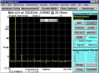
I replaced the TIP41C with 2SC6144 on one channel. Running both at 350mA bias, the THD at 1kHz, 2VRMS, 20 Ohms, on the 6144 side measured 2dB higher (-87 vs -89dB) . I'm guessing this is due to its higher capacitance. Increasing the bias to 400Ma made up the difference. I would take it a tad higher but the heatsinking on the regulator is at it's limit.FYI, Hfe on these 6144's are measuring 500, with good beta Vs Ic linearity up to 1A. Beta vc Vce is not quite as linear as the TTCs. Looking forward to trying them in-circuit.
Tonight I'll install the 6144's in the other channel and do some listening.
Attachments
And the audible result is quite similar to the impact the TTC004B's had in the lower-power version. Punchy. Effortless. Clearer tonal qualities in the fundamental range. Makes the 41C version sound edgy, pinched.
Thanks to Lee for recommending the 2SC6144. Quite a nice device!
Thanks to Lee for recommending the 2SC6144. Quite a nice device!
When planning a headphone amp, I found it useful to plot the data from this Y2013 table at head-fi.org. The class-A bias current needed to drive those headphones to 110dB was not (to me anyway) shockingly high, even with a non-push-pull output stage.
_
_
Attachments
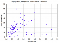
Interesting plot. Curents are lower than I would have surmised, especially considering the 110Db SPL target.
I'm still puzzling over the results in post #46. Despite its vastly greater Hfe and good beta linearity vs Ic, replacing the TIP41C with the 2SC6144 at the same 350mA bias resulted in a THD increase. Just a couple dB, but quite audible.
This was not the case when the TTC004B replaced the TIP41C in the lower-powered version.
What is/are the mechanism(s) that would cause this? My initial guess was the 6144's higher Cob (60pF vs ~20). The only other thing I saw was the Ic vs Vce was not quite as linear (flat) on the 6144.
This was not the case when the TTC004B replaced the TIP41C in the lower-powered version.
What is/are the mechanism(s) that would cause this? My initial guess was the 6144's higher Cob (60pF vs ~20). The only other thing I saw was the Ic vs Vce was not quite as linear (flat) on the 6144.
Maybe higher capacitance is the issue since almost all other metrics of the 6144 are superior.
According to the ST datasheet for the TIP41C, the Cob is 60pF at 10V and 100pF at 0.5V. The SC6144 has 60pF / 180pF respectively, thus almost twice as much at low Vce.
I could well imagine the SC6144 having more base to collector capacitance, which matters once the signal amplitude approaches the power supply rail.
We are talking about an emitter follower application here, right?
Is the stage driving the 6144 able to deal with (presumably) higher capacitive load at high signal levels? Maybe increasing bias of the previous stage or adding a speed-off capacitor could help.
Your observation that further increasing the bias solves the issue could be related to the higher bias helping to clear the charge stored in the B-C cap faster, but this is not too likely given the very high beta.
One trick that helped me a lot to improve EF performance and stability was to increase the base stopper (maybe five times or more) and add a ferrite in parallel to the resistor.
Can you share circuit details?
Thanks Lee. The Chinese 41C's measure better in most respects than the Onsemi or ST data sheets show. Unbiased Cob @ 1MHz is 56pF. My 6144's are 196pF. The TTC004's are 38.
These are the output pair in a scaled-down version of the JLH 1969 amp, a so-called Mini-JLH. Schematic is attached, though almost every part has been changed while optimizing for lowest THD at 2VRMS into 20Ω. The load is a transformer, it's Z drops below 10Ω above 10kHz, so maybe I need to bias it more for that?
It would perhaps be more realistic to say that increasing the bias to 400mA 'partially solved' the THD increase.
Attachments

Last edited:
I see. A circuit like this is obviously very sensitive to each device parameters. Tricky to optimize. Well, it was worth a try, but it looks like the parts are just not well suited for the application then.
Nelson Pass's latest cheap DIY Class-A amp for beginners, uses a cure trick which you may wish to copy. He installs emitter degeneration resistors in the output stage {well actually they're MOSFETs so the resistors are source degeneration} ... ... then bypasses those resistors with low voltage supercapacitors. 3.3 Farads, 2.7 volts, for $1.60 (link). If the emitter resistor is 1.2 ohms, then with 3.3 Farads across it you'll get a low frequency rolloff at 0.04 Hertz which is plenty low enough IMHO.
At 400mA of bias current, the 1.2 ohm resistor drops 0.48 volts, giving greatly enhanced thermal stability at very little penalty in output swing. Might be worthwhile for the output stage pull-down element operating in common emitter.
At 400mA of bias current, the 1.2 ohm resistor drops 0.48 volts, giving greatly enhanced thermal stability at very little penalty in output swing. Might be worthwhile for the output stage pull-down element operating in common emitter.
Which project is it? There are many...Nelson Pass's latest cheap DIY Class-A amp for beginners,
The latest one. The one at the top of the sorted-by-date list, in the "Articles" section on firstwatt.com .
The supercapacitor is called "C6" on the schematic (page 2) and is discussed pretty thoroughly in the circuit analysis (page 9).
The supercapacitor is called "C6" on the schematic (page 2) and is discussed pretty thoroughly in the circuit analysis (page 9).
It seems my choice of a "2V into 20 Ohms" target was overly optimistic. Or 'misunderestimated', to use one of my favorite nonsense words. The load is a transformer, and its impedance ( see attached) drops quickly from 20Ω @ 3kHz to 10Ω @ 12k, bottoming at about 6Ω @ 20kHz. So I changed the target to 15Ω and increased the bias to 500mA, which gives -91dB THD @ 2V RMS. The sound is now more what I had expected/hoped.
I briefly increased the bias even more while monitoring the distortion, and could easily get the THD down to -95, and even lower if I improve the regulator heatsinking to handle it. Until then, it will have to stop at 500mA.
Bottom line, I don't think the 2SC6144's were to blame for this. They are performing quite admirably.
Attachments
- Home
- Amplifiers
- Solid State
- Heatsinking and the Toshiba TTC004B