Well that depends. For me, the preamp sets the tone and the distortion, and is what I have used so far - my 2xEL34 basic amp is "distortion-free" at every stage. So I wanted to experiment with a common low-power design that pushes the output stage to the limit.Can I ask a question @audiostrat; where is that 'guitar amp' distortion generated?
Is it predominantly generated in the output stage or in the stages before that?
Jan
Bare in mind that many amps, like the one I am now building, have a "send-return" loop, which is a signal break-point after the preamp, and before the phase inverter (output stage). So, there are many ways to distort your signal:
-> you can max out the preamp input level and the preamp gain, and have tons of preamp distortion, but keep the signal fed to the output stage low, via the send-return circuit (also works as a "master" volume control - meaning it defines the signal level that will arrive at the output stage), so minimum output distortion
-> you can keep the preamp clean, but insert a boost/distortion effect in the send-return loop, to crank the output stage to heavy distortion
-> you can max out everything and everywhere, and get both preamp and output stage distortion
To sum up, I would say that usually you find designs that either stay relatively clean with a small breakup all the way, or used to distort every stage there is. But if I had to answer your question in Boolean algebra, I would say preamp dominates.
The fins will not be sticking at the back, they will be facing the floor. Regarding the mounting planning, I have already a laser-cut template to ensure every hole will be absolutely correct and aligned. And, grease goes first, then I screw everything together, and solder afterwards.You should be thermally Ok (are the fins sticking out the back, I'm confused, you said chassis Top) but I got to thinking by the time you lay out all the chassis drill-throughs accurately enough (got a milling machine?) and tap the sink + the grease mess you may be better off just getting the rectangular cut out in the chassis to clear the resistors. I guess you could screw it together first.. When you don't need any electrical isolation any kind of washer is just a problem unless you're in some kind of volume production situation where it's just cheaper.
I certainly plan to take and post temperature measurements after the build, yes!
My thinking was, if you generate the 'sound' ahead of the output stage, put some sort of a volume control before the output stage and forget about all that convoluted power resistors and heatsink stuff. It's an abomination 😎
Or get an extra speaker, put both in series and get 1/4 of the output power.
Jan
Or get an extra speaker, put both in series and get 1/4 of the output power.
Jan
In the guitar amp sound world, the idea of getting it in the signal stage and running the power amp linear is like saying all opamps sound the same to an audiophile, only worse.
Last edited:

Most end up using pedals anyways.
When you find out how not good tube power clipping is.
or the same
But outside on the chassis would help with heat
When you find out how not good tube power clipping is.
or the same
But outside on the chassis would help with heat
That's one way to do it. You can also add a diode in the feedback path of an opamp circuit. Or several if you want to tune the clipping characteristic. Peavey has a few patents on tube emulator circuits. Some (many?) still prefer the sound of tubes over emulators, though.A relative of a friend built distortion control for guitar amps by using the CMOS CD4049UB inverting gates. One gate is only a CMOS pair and using a feedback loop will form an inverting amp that is only slightly nonlinear but with soft clipping characteristics. Paralleling all six of them on that chip will get a more linear response, still with soft clipping.
Tom
That's called a preamp /drive with a master volume control. This is already done in most multi channel guitar amps.My thinking was, if you generate the 'sound' ahead of the output stage, put some sort of a volume control before the output stage and forget about all that convoluted power resistors and heatsink stuff. It's an abomination 😎
Or get an extra speaker, put both in series and get 1/4 of the output power.
Jan
Distortion from most output power stage can sound very different.
The so called power soak circuit is a very standard way of doing this.
For 15W peak, I don't think one should make it much more complicated.
@audiostrat I have build quite some guitar amps myself.
I don't know exactly what you want to put on the backside, but I see plenty of space for an additional heatsink.
Even with all the common inputs and outputs (maybe fx send/return) in mind.
I don't know exactly what you want to put on the backside, but I see plenty of space for an additional heatsink.
Even with all the common inputs and outputs (maybe fx send/return) in mind.
Well, as I said, I am experimenting with the sound. If I get a nice, different sound from output stage clipping, I will use the power attenuator often. And, even if I was to incorporate that sound in the preamp, how am I supposed to define it before hearing it (and not going deaf)? 😛 So maybe, if I like the sound, I will try to emulate it in a preamp configuration later. But it's still more work than what I am currently doing, I think.My thinking was, if you generate the 'sound' ahead of the output stage, put some sort of a volume control before the output stage and forget about all that convoluted power resistors and heatsink stuff. It's an abomination 😎
Or get an extra speaker, put both in series and get 1/4 of the output power.
Jan
If it doesn't sound good anyway, there you have it - can't get hot if not used. 😛
Jan, I am an electrical engineer myself (mainly analog electronics field), and I like the attention to detail. Adhering to science, actually. In all my builds, I try to find the best engineering solution, never underestimate factors and sometimes over-engineer just to be on the safe side. But, some things are meant for joy - and a simply-planned combo guitar amp is pretty close to it. I know all this may sound like an abomination, but as JMFahey pointed out, we are not talking best, we are talking adequate. And for me, sometimes just adequate is joyful. At least in an electronics project.
My initial plan involved what you are proposing, but eventually I went for a more user-friendly layout. The faceplates are ready and I am not planning to redesign them, I simply lack the time and appetite. If it goes so wrong it can't be fixed in the existing configuration, I will have learned something and maybe curse a little. But right now I will proceed as it is, not because I despise all your remarks (quite the contrary, of course) - but simply because I don't have the courage to postpone the build.@audiostrat I have build quite some guitar amps myself.
I don't know exactly what you want to put on the backside, but I see plenty of space for an additional heatsink.
Even with all the common inputs and outputs (maybe fx send/return) in mind.
Another (retired) EE here. All of the ideas mentioned above about generating distortion in places other than the output stage are valid. The fact is that virtually none of them including a full DSP box in the FX loop will sound or behave exactly like a pair of EL84's being beat to near death with 10 dB or more of overdrive. From the VOX AC15 and AC30 to the Marshall 18 watt and countless others, this is a proven recipe for a good sounding rock guitar amp. There are countless attenuator boxes available on the market to run the tubes well into saturation and turn down the full metal racket at the same time. It's pretty easy to DIY one too.
The AVERAGE power level that the resistors will see when the amp is cranked hard is probably less than 10 watts total even at a very low power to the speakers (resistors eat it all) because the duty cycle is less than 100% unless you like long winded (speaker to guitar) acoustic feedback driven screams. The resistors will however be seeing something resembling a mangled square wave though.
I built a guitar amp for the Hundred Buck Amp Challenge (a sticky in the instruments and amps section) that used UL84 tubes which are a series string 6CW5 tube that is similar but not identical to the 6BQ5 / EL84. It made about 15 watts cranked from 340 volts of B+. I simply added an "L pad" resistive attenuator from Parts Express similar to this one between the OPT and the speaker jack:
https://www.parts-express.com/L-Pad-100W-Mono-1-Shaft-8-Ohm-260-265?quantity=1
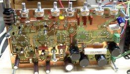
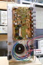
It allows for continuous volume adjustment from zero to cranked and preserves the cranked tone at quiet volumes. I built that amp 12 years ago and never blew the L-pad but it got pretty hot. It was mounted inside the closed chassis though with no heat sinking. The Antek power toroid is being used as the OPT to keep the total cost under $100 (in 2011) to meet the contest rules. The amp worked much better with a real guitar amp OPT. The resistive L-pad is to the right of the OPT in the underneath picture. Yes the amp had far too many gain stages. I added them because 12AX7s would push the cost beyond the limit. The preamp tubes were UCC85's which had about half the gain of a 12AX7. In final form most of the mosfet gain modulation stuff and one whole gain stage was bypassed. The amp has been hiding on a shelf ever since I moved 9 years ago. I have a little 4 tube amp for under $50 in that challenge. It makes all of 4 watts fully cranked, and after tweaking on it for a couple years off and on it's my go to amp now.
The AVERAGE power level that the resistors will see when the amp is cranked hard is probably less than 10 watts total even at a very low power to the speakers (resistors eat it all) because the duty cycle is less than 100% unless you like long winded (speaker to guitar) acoustic feedback driven screams. The resistors will however be seeing something resembling a mangled square wave though.
I built a guitar amp for the Hundred Buck Amp Challenge (a sticky in the instruments and amps section) that used UL84 tubes which are a series string 6CW5 tube that is similar but not identical to the 6BQ5 / EL84. It made about 15 watts cranked from 340 volts of B+. I simply added an "L pad" resistive attenuator from Parts Express similar to this one between the OPT and the speaker jack:
https://www.parts-express.com/L-Pad-100W-Mono-1-Shaft-8-Ohm-260-265?quantity=1
It allows for continuous volume adjustment from zero to cranked and preserves the cranked tone at quiet volumes. I built that amp 12 years ago and never blew the L-pad but it got pretty hot. It was mounted inside the closed chassis though with no heat sinking. The Antek power toroid is being used as the OPT to keep the total cost under $100 (in 2011) to meet the contest rules. The amp worked much better with a real guitar amp OPT. The resistive L-pad is to the right of the OPT in the underneath picture. Yes the amp had far too many gain stages. I added them because 12AX7s would push the cost beyond the limit. The preamp tubes were UCC85's which had about half the gain of a 12AX7. In final form most of the mosfet gain modulation stuff and one whole gain stage was bypassed. The amp has been hiding on a shelf ever since I moved 9 years ago. I have a little 4 tube amp for under $50 in that challenge. It makes all of 4 watts fully cranked, and after tweaking on it for a couple years off and on it's my go to amp now.
Attachments
I am, as we speak, repairing a bunch of power devices that were assembled by someone that didn't know the following:I initially disregarded thermal grease due to being messy, but since everyone suggests it I will go for it. Since I have not used it before, I suppose it does not dry out over time? This was another silly thought that pushed me towards silicone.
You don't need much grease. Just a smear, to fill the microscopic valleys in the surfaces. It's not a great thermal conductor so if you use too much it actually degrades performance.
The newby that built the devices that are currently covering me, my clothes and my bench in horrible sticky gunk clearly thought it was to be spread like Camembert on a baguette.
Yes, the Marshall 18W output stage is what I'm going for. And, exactly because I knew that the real power dissipated in the resistors will not be 15-20W continuous, but lower, as you say, I didn't lose my sleep over the heatsinking of the attenuator. I often listen to metal music, but never play it, so I will not be putting brick waveforms on the attenuator...... From the VOX AC15 and AC30 to the Marshall 18 watt and countless others, this is a proven recipe for a good sounding rock guitar amp. There are countless attenuator boxes available on the market to run the tubes well into saturation and turn down the full metal racket at the same time. It's pretty easy to DIY one too.
The AVERAGE power level that the resistors will see when the amp is cranked hard is probably less than 10 watts total even at a very low power to the speakers (resistors eat it all) because the duty cycle is less than 100% unless you like long winded (speaker to guitar) acoustic feedback driven screams. The resistors will however be seeing something resembling a mangled square wave though.
For testing purposes, of course, I plan to run it for an hour or so maxed out, just to record the temperature. And right now we are in the middle of a heat nightmare in Greece, so with a room temperature of 33-34 degrees Celcius (!) I expect that the testing will be worst-case guaranteed. 🙄
@bremen nacht , thanks for the info! I will try to use as little as possible then, so your clothing sacrifice will not be in vain.
- Home
- Design & Build
- Construction Tips
- Heatsink on top of chassis