Hi there,
This has probably been already explored, but here is my take anyway: heatsinks are generally made of aluminum, so why not use a dissimilar metal connection to make use of the difference in Seebeck's coefficients between the two to evaluate the temperature of the heatsinks? Kind of improvised thermocouple...
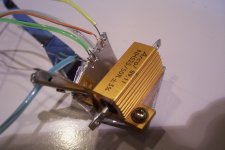
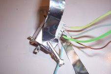
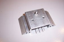
I made a few tests on various commonly available materials in this setup, where the tests leads are crimped into an aluminum plate:
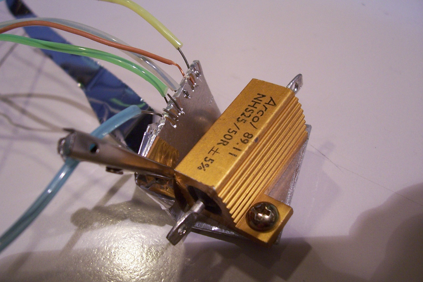
Using an aluminum ribbon as return conductor, here are the voltages measured for T°heatsink ~=100°C (approximate, measured with an IR thermometer, but identical for all samples, thus ΔT=80°C)
One configuration looks particularly promising: the use of Nichrome (resistant wire) as "active", and copper as return: the voltages have opposite polarity meaning a voltage of more than 3mV in total for 80°C, and the ease and convenience of copper as return (which is probably already present as a ground wire).
Nowadays, measuring a few µV's DC is no big deal anymore, provided some elementary precautions are observed, and this method can provide an easy way of directly monitoring the sink's temperature.
The accuracy will be very limited, because the actual thermal voltages depend on the exact composition of alloys, but for overtemperature alarm purposes, it's perfectly OK, and avoids the hassle of drilling + installing a dedicated sensor
This has probably been already explored, but here is my take anyway: heatsinks are generally made of aluminum, so why not use a dissimilar metal connection to make use of the difference in Seebeck's coefficients between the two to evaluate the temperature of the heatsinks? Kind of improvised thermocouple...
I made a few tests on various commonly available materials in this setup, where the tests leads are crimped into an aluminum plate:
Using an aluminum ribbon as return conductor, here are the voltages measured for T°heatsink ~=100°C (approximate, measured with an IR thermometer, but identical for all samples, thus ΔT=80°C)
Code:
Kovar              -971µV
Nichrome           -2960µV
Galvanized iron    +1031µV
Copper             +254µV
Tin-Lead solder    0
One configuration looks particularly promising: the use of Nichrome (resistant wire) as "active", and copper as return: the voltages have opposite polarity meaning a voltage of more than 3mV in total for 80°C, and the ease and convenience of copper as return (which is probably already present as a ground wire).
Nowadays, measuring a few µV's DC is no big deal anymore, provided some elementary precautions are observed, and this method can provide an easy way of directly monitoring the sink's temperature.
The accuracy will be very limited, because the actual thermal voltages depend on the exact composition of alloys, but for overtemperature alarm purposes, it's perfectly OK, and avoids the hassle of drilling + installing a dedicated sensor
Attachments

One why not reason might be that a simple diode clamped to the heat sink or to a transistor body, has worked just fine for decades. Or a small transistor. What is the incentive to make it more complex? I am assuming we are sensing heat for the purpose of tracking bias current as temperatures rise. If the academic question is what is the actual temperature of the heat sink, then I suppose.
Ah, another classic Elvee thread. I bet Jim Williams would've loved this one 😀
This only seems applicable for the (admittedly common) case of a grounded heatsink. At least I imagine trying the same in the face of full rail voltage or even output signal (as seen in some concepts) as common mode component would prove challenging at the very least... we are talking roughly 100 dB CMRR.
And then, of course, there's the question of whether the circuitry needed to reliably detect voltages around a mV isn't actually more expensive than a conventional temp sensor arrangement, which it might very well be.
Interesting idea nonetheless.
Interesting Thermocouple idea!
Note that a 10k Murata NTC costs 16c (0805) from Mouser (+-3 deg C). They are cheap enough to be able to dot them around your board for both overtemp and also for temp comp.
Note that a 10k Murata NTC costs 16c (0805) from Mouser (+-3 deg C). They are cheap enough to be able to dot them around your board for both overtemp and also for temp comp.
One why not reason might be that a simple diode clamped to the heat sink or to a transistor body, has worked just fine for decades. Or a small transistor. What is the incentive to make it more complex? I am assuming we are sensing heat for the purpose of tracking bias current as temperatures rise. If the academic question is what is the actual temperature of the heat sink, then I suppose.
If everybody thinks like that, we would have remained in 19th century.

If everybody thinks like that, we would have remained in 19th century[/quotte]
Not fair, gannaji, I was just asking what the perceived benefit from this new approach might be, what the application demands, where it would be useful.
I can look at a common TL072 dual op amp. We have used them for decades. They work well. If someone proposed making the same overall IC internal circuit for a preamp out of all discrete components, I'd have to ask why. If someone proposes a new dual op amp with better slew rate, better common mode rejection, or whatever, the benefits may be obvious.
I think most designers look to simplfy rather than make things more complex. If they have a good reason to make a circuit more complex, I think it reasonable to ask what that reason is, as I did above. The OP did in fact ask "why not".
Then your question is fair !🙂If everybody thinks like that, we would have remained in 19th century[/quotte]
Not fair, gannaji, I was just asking what the perceived benefit from this new approach might be, what the application demands, where it would be useful.
If everybody thinks like that, we would have remained in 19th century[/quotte]
Not fair, gannaji, I was just asking what the perceived benefit from this new approach might be, what the application demands, where it would be useful.
I think most designers look to simplfy rather than make things more complex. If they have a good reason to make a circuit more complex, I think it reasonable to ask what that reason is, as I did above. The OP did in fact ask "why not".
We should be asking these questions to Pharmaceutical companies for sure🙂
The intention is not to use this as a substitute for conventional bias spreaders: too much scaling, conditioning and translation to do.If the academic question is what is the actual temperature of the heat sink, then I suppose.
As a general purpose temp sensor (for fan control, temperature alarm, ...) though, it could sometimes be advantageous: most heatsinks have tapped holes here and there, or even already used holes, and screwing a crimp ring with the NiCr wire would be easy, as easy a thermistor with a ring mount, but with the advantage of a better thermal contact with the object to monitor, since the object is the sensor.
The cost of the sensor itself is ~=0: I have spools of hundreds of meters of NiCr, and they cost perhaps 25€.
Sure, an IC like the OPA333 costs ~50c, a bit more than the LM358 you would use for other types of sensors, but the difference is not that huge, and if it simplifies the installation, it could be worth itAnd then, of course, there's the question of whether the circuitry needed to reliably detect voltages around a mV isn't actually more expensive than a conventional temp sensor arrangement, which it might very well be.
Sure, it is an option too, but in either case the cost is not really in question as it will be low anyway.Interesting Thermocouple idea!
Note that a 10k Murata NTC costs 16c (0805) from Mouser (+-3 deg C). They are cheap enough to be able to dot them around your board for both overtemp and also for temp comp.
Ease of installation, depending on the actual context is more important: for PCB sensing, a thermistor is certainly easier, but for heatsink contact, thermocouple is probably more effective
Yet another option, but the kind I don't like, because it's not a commodity component.Hi,
I have an easy solution and it is easy to mount in the heath sink. Attached it is a picture. Just one hole to mount it.
In addition, you need to solder wires, use heatshrinking tubing, etc. Not a big deal, but a constraint nonetheless
Be aware of the fact that thermocouples only measure the temperature difference between your intended junction heatsink-NiCr and the inevitable second junction between the NiCr and the rest of the circuit. If you do not keep the second junction at a defined temperature as a reference, there is no reliable temperature measurement this way...
Regards,
Rundmaus
Regards,
Rundmaus
Thermocouple measurements are indeed relative, and for metrological applications, a cold junction compensation is required.
If such an accuracy is needed, just forget this scheme: the compensation circuit is in itself an absolute temperature measurement, and having two measurement systems for "simplification" purposes clearly makes no sense
If such an accuracy is needed, just forget this scheme: the compensation circuit is in itself an absolute temperature measurement, and having two measurement systems for "simplification" purposes clearly makes no sense
It's not the accuracy that's bothering me... But the cold junction is within the housing of the amplifier: If a problem occurs that makes the amp run too hot, the temperature within the housing will also rise, and the measured temperature difference between heatsink (hot junction) and somewhere else in the housing (cold junction) might be significantly smaller than the real temperature of the heatsink with respect to the surrounding room. This could mask any temperature rise due to a fault - not a good behaviour for a safety net, which heatsink temperature monitoring usually is.
Regards,
Rundmaus
Regards,
Rundmaus
Good to bring us the principles into mind but remember the main argument was to
Have fun, Toni
avoids the hassle of drilling + installing a dedicated sensor
Using this "new idea"
- we would need to mount different metals (drilling;screws?)
- avoid oxidation
- need to know the reference temperature
- need a sensitive opamp and maybe and ADC too to measure the low voltage
Have fun, Toni
The point Enzo makes is that a *silicon diode* tracks perfectly a bipolar transistor BE junction **which is also a silicon diode** ... so Enzo is *starting* with a "round wheel"
Now somebody has invented a "square wheel" , because it does NOT track what happens on the self heating diode which is part of a transistor, and will require complex processing to do so, and somehow it should be hailed as the "modern, thus better" solution? :O
Think again. 😉
For the non Tech educated who does not get it:
1) the power transistor BE junction, which is what we want to keep properly biased , that´s the point of this discussion and nothing else, drops 2mV less per every degree C temperature rises.
2) the thermal compensation diode or the thermal compensation transistor also drops 2mV less per every degree C temperature rises.
Somebody might think otherwise, but to me that looks like a perfect match 😉
3) the suggested thermocouple rises a few *micro* volts per Deg C temperature rise, so not only the value is very low and requires lots of amplification, but it also goes the wrong way, since it goes *up* with temperature.
My point is that I don´t care whether something is old or new, only that it *works*.
Round wheels do not come from 19th Century by the way, but are some 5000 years old ... should we discard and replace them with "modern square wheels"?
I guess somebody is missing the point here.
I guess somebody is missing the point here.
Indeed:
The intention is not to use this as a substitute for conventional bias spreaders: too much scaling, conditioning and translation to do.
It's not the accuracy that's bothering me... ...
....
I think you both aim at the wrong target: I never said that this was the system to advantageously replace all existing solutions, with no drawbacks at all.Good to bring us the principles....
.....
It is one alternative among many possible, and sometimes, it could prove advantageous
avoids the hassle of drilling + installing a dedicated sensorUsing this "new idea"
- we would need to mount different metals (drilling;screws?)
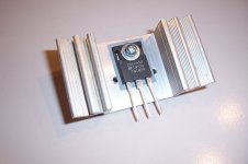
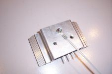
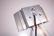
Doesn't seem that insurmountable: here is an illustration:
Start with a naked transistor + heatsink:
Nothing special:
Now, we add the sensor wire:
It could be that the sink is not yet grounded, in this case a ground wire can be added:
Why would oxidation be more problematic here than in other cases? Nichrome is not particularly prone to oxidation, quite the opposite in fact[*]avoid oxidation
In an ideal world, yes, but if you look for instance at the thermostat systems of cheap ovens, you realize that tradeoffs are sometimes possible[*]need to know the reference temperature
[*]need a sensitive opamp and maybe and ADC too to measure the low voltage
It is perfectly clear that you dislike the idea, and that no argument could make you budge....IMHO: nonsense. 😉
Further discussion is pointless...
Attachments
commercial amps for PA where reliability matters use bjt for sensing heatsink temp to control a set of fans and further to display the heatsink temp
If using NTC ( or PTC for that matter) PCB mount sensors, you can do better than trying to measure the heatsink temp: you measure the output transistor collector lead temp, which is in effect the die header temp. On a power transistor, the die will only be 1 or 2 degrees hotter and the response of course is very fast.
I've been using a BC847C like this for temp comp and it works extremely well.
I've been using a BC847C like this for temp comp and it works extremely well.
- Status
- Not open for further replies.
- Home
- Amplifiers
- Solid State
- Heatsink as implicit sensor for temperature monitoring