Hi Every one,
I have just found the instruction manual for an old heathkit EA-2 amplifier, its looking very similar to what I am looking in to building. Does any one have experience of this circuit ?
Also is the ECF82 a good choice for triode pentode or would a 6BR8A be a better option ?
Cheers,
Matt
I have just found the instruction manual for an old heathkit EA-2 amplifier, its looking very similar to what I am looking in to building. Does any one have experience of this circuit ?
Also is the ECF82 a good choice for triode pentode or would a 6BR8A be a better option ?
Cheers,
Matt
Be a little more specific about what you want.
Do you want the amp to be just a power amp?
Do you want the amp to have tone controls?
How many watts do you want?
What kind of Loudspeakers will you be driving with the amp?
What kind of topology do you want?
Triode wired
Ultra Linear
Pentode
Negative feedback for the Pentode, Ultra Linear, and perhaps on the Triode wired?
Push Pull
Why are you mentioning the ECF82 and 6BR8A?
Are you planning to use the pentode as the gain stage, and the triode as the concertina phase splitter?
There are lots of schematics out there, what was it about the Heathkit E-A2 that attracted you?
The heathkit looks simple, I am planning on a small push pull amplifier 5+ watts for a desk. 300mV input and a 8ohm out put with a volume control on the front, a headphone monitor would be a plus point.
I was looking in to pentode input stage, triode concertina phase splitter. Then a pair of EL84's in ultra linear with a 43% tap on a 8K transformer. I want to keep it simple and it will all be built on tag strip, HT of around 300V from a GZ34. DC heaters to front end valves and AC for power valves.
I have some 6BR8A and ECF82, plus many of the ECC range and EL34/84 valves. Plus many I cant place, left overs from a departed friend.
The concertina triode with the "floating' cathode 'might' benefit from DC filaments. Otherwise, I do not see a reason for DC filaments unless you are going to have a phono preamp as the first stages.
You are talking about designing your own pentode and concertina stages if you use the ECF82 or 6BR8A (I do not think you will find an amplifier circuit with those). The plate of the pentode may need a dominant pole to ground to make negative feedback stable (depending on the rest of the amp, and the output transformers). Ultra Linear usually needs negative feedback to get the damping factor up.
A typical AC line operated CD player has 2Vrms out (2.8Vpeak). It does not take very many stages to get the gain you need for 5+ Watts.
You can find lots of EL84 amplifier circuits on this forum.
Wow, that's almost spot on to what I was thinking, huge thanks Alan. I may well build that, just waiting for a price on transformers.
Huge thanks every one.
Huge thanks every one.
6BR8 may be hard to find as replacements. It was originally designed as a 6U8 with a special pinout, and 6U8/ECF82 has numerous substitutes, which would at worst require a resistor value change. 6EA8, 6GH8, 6KD8, 6BL8, ECF80, and numerous others. (On the other hand, NOBODY uses 6BR8s, so there may be some around forever...)
Ooooh thanks for the reminder, I may need to buy about 30 for storage then as I have a stereo amp, 4 mono blocks and a pre amp all using this valve. Need to find stereo amp!
Hi Every one,
I am just starting to get bits together for this and order the transformer, I have just built the front end stages. Input and phase splitter to test, running of an old 220V 50mA transformer.
It all works well, 200mV in and 48V out at 1KHz, about 50V at 100Hz. Sadly its dropping off sharply over 10KHz and dropping to 28V, this is all unloaded and without the output stage or out put transformer, they are still 6 weeks away. I am just wonder if I have done something totally wrong or will the rest of the amplifier compensate for the drop off ?
Phase splitter is working and running about 182 degrees of difference.
Any help greatly received,
Matt
Did you compensate your scope probes using the scope square wave? Are you using the 10X probes (you can not use a 1X probe to test the frequency response of the concertina phase splitter; nor can you use the 1X probe to test 90% of tube stages.
Are you talking about only the 6AN8 pentode and triode stages? Or did you include the tone control driver tube and tone controls? Unless I missed something, the frequency response of the 6AN8 ought to be quite flat.
Does your signal generator have a 600 Ohm output, or 50 Ohm output? A long coax cable (capacitance) and 600 Ohm output do not mix (there can be high frequency rolloff).
Did you mean with a constant 200mV input (refer to the scope probe compensation, and generator output impedance and connections) the outputs were 48V, 50V, and 28V? That is frequency response, but could also be slew rate limiting.
Did you build the tube stage that drives the tone control? You have to find what rotational position on the pots are correct for a flat response. Some tone control pots are linear, some are log taper, audio taper, etc. Rotation to the Mid Point may not be flat, especially if you used the wrong taper.
PRR,
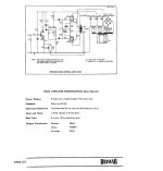
This thread had been latent for a while, so . . . I did not re-read through the thread and find that this might be built to the Brimar amp spec. I thought this was for a Heathkit E-A2 amplifier. The schematic I got off the web did not have that dominant pole. (I looked for it, because that was my first thought). There must have been more than one version of E-A2, or we are now talking about the Brimar amp. Start with the exact schematic, or get in-exact performance.
This thread had been latent for a while, so . . . I did not re-read through the thread and find that this might be built to the Brimar amp spec. I thought this was for a Heathkit E-A2 amplifier. The schematic I got off the web did not have that dominant pole. (I looked for it, because that was my first thought). There must have been more than one version of E-A2, or we are now talking about the Brimar amp. Start with the exact schematic, or get in-exact performance.
Last edited:
...Heathkit E-A2 amplifier. The schematic I got off the web did not have that dominant pole....
Here.
Attachments
Yes I built the Brimar 6br8 input stage, I will take a look at the 470k and 33pf combo.
I am using an ap 515 and short cables for all test, my lack of valve experience is showing.
Cheers every one
I am using an ap 515 and short cables for all test, my lack of valve experience is showing.
Cheers every one
Actually, the 470k is the pentode plate load. The 10k and 33pF is the dominant pole roll off filter. The amp uses negative feedback. The dominant pole is in parallel with the 470k plate load, it helps increase the amplifier stability. It is a way to deal with the total power amplifier circuitry, particular output transformer, and negative feedback circuitry. The total gain versus frequency, and phase versus frequency will cause oscillation if that is wrong (and may vary versus loudspeaker load too).
> 10k and 33pF is the dominant pole roll off filter.
To most amp designer thinking, the 33pFd against the 470K (||rp which is large) is "the dominant pole". It "dominates" the important range above 10KC, where several unavoidable poles stack-up and phase goes screwy. By "dominating" it gets gain down so loop-phase does not go unstable before loop-gain gets below unity.
The 33pFd against the 10K sets a secondary zero up around 500KHz. By this point we are near stable, and we can drop-out this network, let the multiple inherent poles do their things.
PRR,
You are right again. I incorrectly called the 33pF and 10k the dominant pole. Some amps do not use a dominant pole that is a strict RC network. Remove the 33k and 10k, and the 470k merely becomes a plate load; but with the 33pf becomes the dominant pole. That was a good explanation of the whole circuit, including the second zero.
You are right again. I incorrectly called the 33pF and 10k the dominant pole. Some amps do not use a dominant pole that is a strict RC network. Remove the 33k and 10k, and the 470k merely becomes a plate load; but with the 33pf becomes the dominant pole. That was a good explanation of the whole circuit, including the second zero.
- Status
- Not open for further replies.
- Home
- Amplifiers
- Tubes / Valves
- Heathkit EA-2