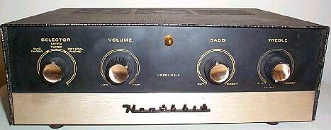
I got two of these from the local CraigsList:
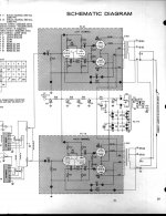
The schematic:
I'd like to convert these two mono "integrated amps" into two simple power amplifiers.
Am I correct in thinking:
There's a 12AX7 tube used (one of the two grids) for phono amplification. The other grid is the first voltage stage for the amp. Since I'm converting this to a power amp, that phono grid can be tossed out. It may be easier to run a single-triode instead of the dual-triode 12AX7 in this spot. This will raise the heater voltage (nominally 12 volts) to about 14 volts. With that extra 2V to play with, I can rectify the AC heater voltage to DC with a diode & a capacitor. This alone should significantly improve the signal to noise ratio?
I can throw out the input selector switch and two of the three input jacks, replacing the remaining jack with a higher quality RCA jack.
I can throw out the volume control pot and tie the anode between the first tube to the grid of the first 6C4.
I can throw out the bass & treble control pots, resistors, & caps downstream of the first 6C4 and route the filtered signal from the 6C4 anode to the grids of the 6AN8 (the phase splitter)
The EL84s can remain untouched.
The 16-ohm output tap can be severed, and 5-way binding posts installed for the ground, 4-ohm, & 8-ohm taps.
The B+ supply voltage should be OK, but if it becomes too high with the deletion of the phono tube, I may have to regulate it too?
Suggestions appreciated.
The schematic:
An externally hosted image should be here but it was not working when we last tested it.
I'd like to convert these two mono "integrated amps" into two simple power amplifiers.
Am I correct in thinking:
There's a 12AX7 tube used (one of the two grids) for phono amplification. The other grid is the first voltage stage for the amp. Since I'm converting this to a power amp, that phono grid can be tossed out. It may be easier to run a single-triode instead of the dual-triode 12AX7 in this spot. This will raise the heater voltage (nominally 12 volts) to about 14 volts. With that extra 2V to play with, I can rectify the AC heater voltage to DC with a diode & a capacitor. This alone should significantly improve the signal to noise ratio?
I can throw out the input selector switch and two of the three input jacks, replacing the remaining jack with a higher quality RCA jack.
I can throw out the volume control pot and tie the anode between the first tube to the grid of the first 6C4.
I can throw out the bass & treble control pots, resistors, & caps downstream of the first 6C4 and route the filtered signal from the 6C4 anode to the grids of the 6AN8 (the phase splitter)
The EL84s can remain untouched.
The 16-ohm output tap can be severed, and 5-way binding posts installed for the ground, 4-ohm, & 8-ohm taps.
The B+ supply voltage should be OK, but if it becomes too high with the deletion of the phono tube, I may have to regulate it too?
Suggestions appreciated.
You can simply feed the input signal to the grid (pin 8) of the 6AN8. Add a resistor to ground something in the order of 200-470K and it should work fine. Then ditch everything in front of that point. If you keep the 6C4, you will have way too much gain.
6BQ5/EL84's don't need very much drive.
You needn't worry about much of a change in B+ by removing the other tubes as they draw very little current.
You should replace the filter caps because they are really old now. Sounds like a fun project and good luck.
6BQ5/EL84's don't need very much drive.
You needn't worry about much of a change in B+ by removing the other tubes as they draw very little current.
You should replace the filter caps because they are really old now. Sounds like a fun project and good luck.
Last edited:
Thank you most kindly - I know just enough to be dangerous! LOL
The filter caps were changed in 2014.
The filter caps were changed in 2014.
The 16 Ω tap can be "buried", but not eliminated. Please observe that the 16 Ω tap is where GNFB is taken from.
The high gain pentode voltage amplifier may lead to a "hair trigger" volume control, when combined with modern 2 VRMS digital sources. Some of that gain was needed to compensate for the losses in the tone control circuitry that's being eliminated. That schematic is similar to the Dyna SCA-35, which also contained lossy tone control circuitry.
Be "kind" to the EL84/6BQ5 O/P tubes. Mount 1 W./100 Ω carbon film safety/stopper resistors at the g2 socket lugs in the lines leading to the UL taps.
All of the popular pentode/triodes, including the 6AN8, are out of production and supplies are disappearing, if not already gone, rapidly. The issue can be worked around in more than 1 way. I'll go into detail, if asked.
Attachments
My game plan is to replace all remaining resistors with metal film ones of 2X the original wattage dissipation. My game plan is to also replace all remaining signal capacitors with film-dielectric ones of 2x the original voltage rating.
Your comment on the 16 ohm tap GNFB is noted - thanks!
I'll also take your suggestion on the stopper resistors.
Now two further questions, if you'll be so kind - what, if anything should I do to compensate for the high gain of the 6AN8?
Also, if you would kindly elaborate on alternatives to the existing (and discontinued) tubes?
Thanks most kindly, Eli!
Boomzilla
Mix signal cap. dielectric materials up. Hear the amp, not the capacitors. 😉 Soviet surplus K40 PIO and 716P series "Orange Drops" are what I'd look into.
Low noise metal film resistors are fine in grid to ground positions and 1/2 W. parts are all that's needed. Either carbon film or Mills non-inductive wirewound parts are "best" for plate loads and cathode bias resistors. Metal film parts in those positions have a reputation for making an amp sound "icy cold".
High pentode voltage gain gain be dealt with by "padding" resistors at the I/Ps or reducing the anode load resistance value. Reducing the load resistance is more "elegant", but getting the operating conditions sorted out is not a trivial exercise.
I like to see high transconductance devices used in circuitry containing GNFB loops, as protection against HF error correction signal induced slew limiting. Let me give the matter some thought. Are you adventurous?
You can emulate a pentode/triode by using an EF86 and 1/2 a 12BH7. No high gm here, but the the types are in production. Wire 1 amp to use system "A" of the twin triode and the other amp to use system "B". When the tubes show signs of wear, exchange them and double the service life.
My goals are durability, better sound than original, minimal parts count, and ready availability of spare parts, in that order.
I completely agree with Eli if you want to take the design beyond stock. I would suggest you start with something based upon the original schematic then add changes and listen for any changes/improvements along the way.
This is the where the real fun and learning process happens, IMHO.
This is the where the real fun and learning process happens, IMHO.
MAJOR ROADBLOCK: There are two industrial electrical stores in town. At one time they both stocked large supplies of resistors and capacitors. Now, neither do.
I've looked online (eBay, Moser, etc.) for the values / voltages I need, but they are no longer available. WHERE does one go to find odd capacitors?
I need 0.1mF @ 600v (the only ones I've been able to find)
0.05mF @ 600v
220pF @ 600v
33pF @ 600v
Any ideas?
I've looked online (eBay, Moser, etc.) for the values / voltages I need, but they are no longer available. WHERE does one go to find odd capacitors?
I need 0.1mF @ 600v (the only ones I've been able to find)
0.05mF @ 600v
220pF @ 600v
33pF @ 600v
Any ideas?
Are 600 WVDC caps. really necessary in a 6BQ5 amp? I would think 400 WVDC parts are adequate.
Cap. values have been standardized, since the EA-2 was designed. Use 0.047 muF., instead of 0.05 muF. The small difference is well within manufacturing tolerances.
Start with the B+ PSU. Use a CLC filter to feed the O/P tubes, not a cheap single capacitor. 😡 A 33 muF. metallized polypropylene part at the filter's I/P will slightly reduce the strain on the EZ81/6CA4 rectifier, without adversely impacting performance, whatsoever. AAMOF, a small improvement is likely. A modestly priced Triad C-14X will do very nicely as the filter choke. Use a 100 muF. 'lytic in the reservoir position. Now, the amp will play bass, without "falling apart". 😀
Given that tri-pents are out of production, the EF86/12BH7 combo will have to be implemented. The Triode Electronics replacement driver board for Dyna ST-70s uses the method. It's well proven. 😉
My preference in designs, like this, employing GNFB loops is to roll infrasonic noise off at the I/P and limit phase shifts inside the NFB loop. Protecting the O/P trafo against core saturation from an excessive LF error correction signal is the primary reason. The coupling caps. between the phase splitter and "finals" increases to 0.1 muF., in this scenario.
DC heaters are an unnecessary frill in a power amp. What can be considered is biasing the heater supply off B+ at about 60 V.
Don't forget a proper, 3 wire, safety grounded, power cable.
Cap. values have been standardized, since the EA-2 was designed. Use 0.047 muF., instead of 0.05 muF. The small difference is well within manufacturing tolerances.
My goals are durability, better sound than original, minimal parts count, and ready availability of spare parts, in that order.
Start with the B+ PSU. Use a CLC filter to feed the O/P tubes, not a cheap single capacitor. 😡 A 33 muF. metallized polypropylene part at the filter's I/P will slightly reduce the strain on the EZ81/6CA4 rectifier, without adversely impacting performance, whatsoever. AAMOF, a small improvement is likely. A modestly priced Triad C-14X will do very nicely as the filter choke. Use a 100 muF. 'lytic in the reservoir position. Now, the amp will play bass, without "falling apart". 😀
Given that tri-pents are out of production, the EF86/12BH7 combo will have to be implemented. The Triode Electronics replacement driver board for Dyna ST-70s uses the method. It's well proven. 😉
My preference in designs, like this, employing GNFB loops is to roll infrasonic noise off at the I/P and limit phase shifts inside the NFB loop. Protecting the O/P trafo against core saturation from an excessive LF error correction signal is the primary reason. The coupling caps. between the phase splitter and "finals" increases to 0.1 muF., in this scenario.
DC heaters are an unnecessary frill in a power amp. What can be considered is biasing the heater supply off B+ at about 60 V.
Don't forget a proper, 3 wire, safety grounded, power cable.
To start, I plan to implement Dilbert's rec & just toss out everything upstream of the 6AN8 tube. Everything downstream remains stock until I listen to it. Then we'll see...
MAJOR ROADBLOCK:
I need 0.1mF @ 600v (the only ones I've been able to find)
0.05mF @ 600v
220pF @ 600v
33pF @ 600v
Any ideas?
Yes, I have an idea.
You should anticipate that the workers registrering stock have no idea what they're doing 😀
Mouser (Not Moser) lists Wima 220pF/650VAC-1600VDC Polypropolene cap's and they are among the best imho.
To find them you'll have to search for 0,22nF and NOT 220pF capacitors.
Mouser Partno.: 505-FKP1T002204BJI00
Wima 33pF/250VAC-1KVDC Polypropolene cap's are partno.: 505-FKP233/1000/10
Vishay 47nF/250VAC-630VDC Polyester MKT, Axial cap's are partno.: 75-MKT1813347635
Last edited:
Found them all - thanks. I've also implemented Mr. Dilbert's recommendation & disconnected everything upstream of the 6AN8. Works fine - better sound than before.
But one amp still has more gain than the other, and the louder of the two seems to have some slight distortion. I'm assuming that this is in the output tubes or the 6AN8. I swapped the rectifier tube between the two amps, and the "weak" amp still remained the weaker of the two.
So decision time - Are these worth the tube replacement cost? They DO sound muddy in the bass and "hooded" in the midrange. Not sure if that's from the resistors/caps, from the tubes themselves, or from the transformers...
Ideas?
Ideas?
Sure! Whether you are interested or not is TBD.
Remember, I previously posted about infrasonic noise filtering. That can help with "tubbiness". In circuitry with GNFB, the NFB resistor pair is the determining factor of end result gain. Your parts were not precise, to begin with, and they may have drifted too boot. That could account for the inconsistent behavior between the 2 monoblocks.
I'm guessing you have a preamp with some gain. If you strip away all the unwanted/unused controls, space is gained in which a small toroidal trafo, to energize a negative rail, is mounted. Convert the units to ultra-linear mode "El Cheapo" topology, but use a 7 pin mini 6J6, instead of a 12AT7, for the splitter/driver. Yes, the 6J6 is out of production, but (unlike tri-pents) supplies are plentiful. Contact Jim McShane for the correct parts values in the O/P tube cathode bias RC networks. The 'AQ5 shown in the uploaded schematic is a member of the 6V6 "clan" and the appropriate values are somewhat different.
Attachments
Maybe you want to check all the resistors for drift, especially in the feedback network, including the cathode resistor of the pentode portion of the 6AN8, first.
Then, check or replace the tube as well.
Then, check or replace the tube as well.
Thanks again, gents. At this time, I don't think I want to go with a ultra-linear setup with this project.
But I have new resistors (+/- 0.5%) and plan to just replace them all. Ditto with new caps.
Here's the original chassis:
I'll post some "after" photos when I'm done.
But I have new resistors (+/- 0.5%) and plan to just replace them all. Ditto with new caps.
Here's the original chassis:
An externally hosted image should be here but it was not working when we last tested it.
An externally hosted image should be here but it was not working when we last tested it.
I'll post some "after" photos when I'm done.
At this time, I don't think I want to go with a ultra-linear setup with this project.
Ultra-linear means O/P tube screen grids connected to taps on the O/P transformer primary. That's exactly what Heath did. 😉 I suggested you change the small signal circuitry, not the power O/P configuration.
FWIW, approx. 355 V. of B+ are needed in an "El Cheapo". That could require switching to SS rectified B+. The 6CA4 would switch from B+ rectifier to being part of the hybrid bridge B- rectifier. 😀
- Status
- Not open for further replies.
- Home
- Amplifiers
- Tubes / Valves
- Heathkit EA-2 customization