Hey All,
Is there anyone out there familiar with a Heathkit audio analyzer? Its a model IM - 22. I'm trying to use it to set AC balance on my Dynaco's. I'm really having a problem understanding the instructions. I did manage to get a reading and by using the pot on the inverted side of the phase splitter I was able to adjust it to a lower setting. But I can't figure out what the meter is telling me? And I want to know how much IM distortion there actually is?
Kevin
Last edited:
Normally you would use a thd analyzer to set the AC balance pot.
Obviously this is not a standard Dynaco amp design since they did not have AC balance pots, and only a single bias pot per channel so you will need to fill in some details about what you are adjusting in the amp to get a useful answer.
IMD is measured by mixing two specified tones in a specific amplitude ratio depending on the standard followed. The analyzer looks for the product and difference tones produced by the DUT and usually expresses them as a % or dB value relative to the amplitude of the composite tone. (Generally specified in terms of rms) Not sure what the Heathkit is actually doing. Lower is obviously better.
Thanks Kevin,
So I can't use an IM analyzer to set AC balance? I guess I'll need another piece of equipment!
The amp started as a Mark VI. It now has a 6CG7/6CG7 front end using a long tail pair. The outputs are KT88's. Individual coupling caps and individual bias pots.
So AC balance can't be set with an IM analyzer?
That is correct. You should use a total harmonic analyzer. In lieu of that, you can also come very close with a dual trace scope assuming it has an "add" position for the two channels. The purpose of the balance control is to adjust the output amplitude of one of the phases. Either in the cathode or the anode. Since they are in antiphase, connecting each output to a scope channel and "adding" them will null the signal. Adjust the balance control for maxium null. (minimum amplitude) Use 10X low capacitance probes.So AC balance can't be set with an IM analyzer?
That is correct. You should use a total harmonic analyzer. In lieu of that, you can also come very close with a dual trace scope assuming it has an "add" position for the two channels. The purpose of the balance control is to adjust the output amplitude of one of the phases. Either in the cathode or the anode. Since they are in antiphase, connecting each output to a scope channel and "adding" them will null the signal. Adjust the balance control for maxium null. (minimum amplitude) Use 10X low capacitance probes.
In full agreement with this. I use the scope methode for setting the AC balance on my Citation II. Of course, you also need a signal generator which can come from a free smartphone app.
Last edited:
I have a dual trace scope and a signal generator. And the scope has an add function. But if that's the case, couldn't you just put DVOM, set for AC, leads on either phase inverter output and adjust for zero?
I'd use the scope, unless you are sure the meter you have responds accurately at audio frequencies. (I have 3 that do, but they are not the inexpensive handheld examples found on eBay either.) Being able to see the null with a scope makes the adjustment easier IMO.
It's been a long time since I had to do this adjustment, my current amps are all SE, and even my older PP designs did not feature this adjustment. 😀
It's been a long time since I had to do this adjustment, my current amps are all SE, and even my older PP designs did not feature this adjustment. 😀
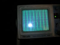

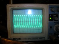
They look as they should look. Of course you will get the best success when both scope channels are well calibrated and have exactly the same gain. This will set the phase inverter stage to it's optimum. But that's all it will do. Using a THD analyzer on the speaker output will allow the balance adjustment to compensate for non adjustable imbalances in the output stage as well, like mismatched tubes or imbalances in the OPT. But these should be at a minimum anyway and I doubt that you'd ever hear small changes there.How's this look? On the left is 'Dual' on the right is 'Add.'
Thanks,
I just listened to the first amp. I made some other drastic changes since I've heard them. On first listen they seem much improved. Much less edge. I added a feedback circuit. It is connected to the 8 ohm tap now. It only sounds good with the pot turned all the way down. I think I'm going to move it to the 4 ohm tap and see what that sounds like. I bought a Heathkit THD analyzer off eBay today. When I get it I will revisit the issue.
Thanks for all the help so far, Kevin
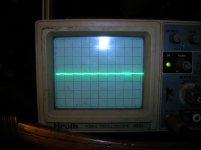
AC Balance Waveform
Does this look better? I used the different leads back and forth so they measured the same waveform. But to get there the settings weren't the same? Is it possible the leads are somehow different? Then I only had a very narrow window on the pot so I had to futz with the in phase plate resistors to get the best adjustment.
I still have a THD analyzer on the way. When I get it I'll try the speaker output method. I'm assuming that will take into account the output transformer and give an even closer adjustment?
Attachments
Last edited:
Do your probes have capacitance adjusters?
Let the scope warm up for 20min then adjust to achieve a nice flat-top waveform from a known good square wave source.
Let the scope warm up for 20min then adjust to achieve a nice flat-top waveform from a known good square wave source.
I bought a Heathkit THD analyzer as well. Can you use it to adjust feedback? On the spectrum of feedback adjustment there must be point where feedback ceases to reduce distortion and begins to deaden the sound. Could a THD analyzer be used to pinpoint this level of feedback?
I have some pretty decent test hardware, and have not been able to establish any such relationship which is actually a good thing since it flies in the face of feedback theory. As long as you have available open loop gain and have not reached unity noise gain the distortion generated inside the loop will continue to decrease, at some point you may no longer be able to observe it due to limitations in test equipment (this is a recurrent problem with latest generation of op-amps and special measurement techniques have been developed to deal with it) another issue is components external to the circuit such as switches, pots and relay contacts.
In theory this is possible but only to a degree. But your Heathkit analyzer won't do this because it's really only made for static measurments. And the reason is because as feedback is adjusted up or down, the amplifier's output level changes. This would require an analyzer with an auto set level function to compensate for the varying input. Otherwise you would have to constantly reset the input level after every adjustment. This would be very tedious and become frustrating pretty quickly. And those analyzers, like HP's or Sound Technology's, with auto set level have a limited dynamic range for that function. Unfortunately when you move away from Heathkit stuff things become a lot more expensive.I bought a Heathkit THD analyzer as well. Can you use it to adjust feedback? On the spectrum of feedback adjustment there must be point where feedback ceases to reduce distortion and begins to deaden the sound. Could a THD analyzer be used to pinpoint this level of feedback?
Last edited:
- Status
- Not open for further replies.
- Home
- Amplifiers
- Tubes / Valves
- Heathkit Audio Analyzer