Ya I was thinking some more and things actually cancel as far as any AC induction in the grid. I would also suspect if it was happening you could surely measure it. Oh well!
Popilin: Most grids are at pretty much 90 degrees to the filament in DHT's. Are you still going to get any significant voltage induction?
(Well except for where the grid turns and comes back the other way...but then the opposite thing is happening on the other side...hummm)
Still in most designs the effect will actually multiply!!! (Both sides of the grid wire where it turns and comes back the other way are alined to induce a voltage into the grid in the same direction)
Ya ...AC is a bad idea in a DHT.
I have to be honest I never thought of the AC magnetic field introducing a voltage into the grid, but the way most filaments and grids are configured.....it most likely does!
(Note: These are just my thoughts, I am however in agreement with Popilin and his conclusion with regards to a voltage induction in the filament)
Further discussion please..........
Hi MelB
Manufacturers have wit to minimize the influence of AC magnetic field from filament over the grid, however it is impossible that the turns of the grid are perpendicular to the filament, first because the grid have to cover a distance with a finite number of turns, and second, in the case you mention, filament is M-shaped.
But that was the most cheating of reasoning to reach (4) because "turns" are short circuited, and as I mentioned, the grid is almost equipotential, and with a less tricky reasoning, reached a similar result (6).
Not trying to be strictly formal, but to show in a more dramatic, the effect of an AC voltage on the filament.
If you want, you can say it's just marketing.😀
Best regards
Johann
Ya I was thinking some more and things actually cancel as far as any AC induction in the grid. I would also suspect if it was happening you could surely measure it. Oh well!
Yes, and the hum is a product of our imagination.😀
It was enough to what was said in post # 76.
I waste my time and effort in a physical and mathematical demonstration and you do not believe me.
What do you want? A notarized certificate?
Well, I can understand, I'm just a TV repairman.😀
"It is easier to split an atom than to break a prejudice" A. Einstein
I waste my time and effort in a physical and mathematical demonstration and you do not believe me.
What do you want? A notarized certificate?
Well, I can understand, I'm just a TV repairman.😀
"It is easier to split an atom than to break a prejudice" A. Einstein
AC induction into the grid from the heater will be negligible in most situations because the AC will be low frequency 50/60Hz (magnetic induction is proportional to frequency) and the grid in most cases is just a set of single loops (not a solenoid because the grid supports acts as shorts). Where it might matter (low signal audio) the valves intended for this service (EF86, ECC83) have special heater windings to reduce their external magentic field.
Hum is often induced in the grid because the heater voltage is not a nice sine wave. Since it is usually derived from the mains, and often from the same power transformer as the HT, the heater voltage is often ugly, clipped and bent out of shape. It contains plenty of sharp corners (large dV/dt) that couple easily to the grid via stray capacitance, even though the fundamental is only 50/60Hz. The higher the node impedance of the grid, the worse the effect.
This is likely to be a much greater problem than magnetic fields, not only because magnetic fields tend to decay faster with distance than electric fields, so lower-voltage filaments may suffer less from this form of hum.
This is likely to be a much greater problem than magnetic fields, not only because magnetic fields tend to decay faster with distance than electric fields, so lower-voltage filaments may suffer less from this form of hum.
Good point. I think some ECC83 data sheets recommend avoiding 12.6V (AC) heater wiring where low noise is required. The current would of course be exactly the same, but the heater voltage for one of the triodes is higher.
Yes, and the hum is a product of our imagination.😀
Sorry I never said there was no humm only that your proposed mechanism "may" not be correct or more properly "significant".
You are proposing the AC cathode is inducing and voltage in the grid. Yes the cathode is a W shape but is it closer to 90 degrees or is it closer to zero degrees in relation to the grid? So I ask again if the grid is at 90 degrees to cathode how does that impact a voltage induction...as opposed to the grid running parallel to the cathode?
You have three elements in a triode Cathode Grid and Anode. So any voltage MUST be taken in relation to the other two elements. Introducing AC onto ANY one of those elements changes ALL of the relationships with the other two elements over the course of a single sine wave. = Humm
A 6.3 volt AC cathode = more humm than a 2.5 volt AC cathode. It's not more complicated than that. At least that's my take on it.
AC induction into the grid from the heater will be negligible in most situations because the AC will be low frequency 50/60Hz (magnetic induction is proportional to frequency) and the grid in most cases is just a set of single loops (not a solenoid because the grid supports acts as shorts). Where it might matter (low signal audio) the valves intended for this service (EF86, ECC83) have special heater windings to reduce their external magentic field.
It seems to me, and I say with all due respect, you do not read my post properly.
Well, my Tarzan-English does not help much, but don't need a cryptographist.😀
AC induction into the grid from the heater will be negligible in some situations, because
U(grid) ~ (k/N) U(fil) << U(fil)
In the case of a high mu valve, or a DHT, it's becoming more significant.
And magnetic induction B is NOT proportional to frequency
For an Ideal loop where an AC current i(AC) flows with a voltage U(AC), from Maxwell's equations, the AC magnetic field is given by
B(AC) = [ U(AC) x 10^8 ] / [ sqr (2) * (Pi) * S * f ]
Is inversely proportional to frequency, like I told you in post # 41
I think Pete Millett is a smart guy, why would suggest a 100KHz sine wave filament PSU? did not hear about what you say?
I said in post # 98
sic "Ofcourse, a real grid, only "seems" to have turns, in fact it is almost equipotential"
I cleared again in post # 102
sic "But that was the most cheating of reasoning to reach (4) because "turns" are short circuited, and as I mentioned, the grid is almost equipotential, and with a less tricky reasoning, reached a similar result (6)"
Is not that do not believe me, do not understand.
What a pity!, I wanted one of your intelligent discourse on intermodulation.
Best regards
Johann
Another who can not read my post, are boring and convoluted, but to criticize them you must first read them.😉
I clarified to you in post # 102, but you stayed glued with the most cheating of reasoning to reach (4).
Forget the turns, the grid is just an electrode, and with a less tricky reasoning, reached a similar result (6).
I remind you that physics does not change by changing the referential, if you want to complicate things even more, I remind you that Maxwell's equations are Lorentz covariant.
Show me a referential where the triode having less hum.
With math, please, we're talking about physics, not philosophy.
You're right, here seems to understand something of what I said in post # 98
U(grid)(6.3) ~ (k/N) U(fil) = (k/N) * 6.3V
U(grid)(2.5) ~ (k/N) U(fil) = (k/N) * 2.5V
Clearly
U(grid)(6.3) > U(grid)(2.5)
It's not more complicated than that.
Sorry I never said there was no humm only that your proposed mechanism "may" not be correct or more properly "significant".
You are proposing the AC cathode is inducing and voltage in the grid. Yes the cathode is a W shape but is it closer to 90 degrees or is it closer to zero degrees in relation to the grid? So I ask again if the grid is at 90 degrees to cathode how does that impact a voltage induction...as opposed to the grid running parallel to the cathode?
I clarified to you in post # 102, but you stayed glued with the most cheating of reasoning to reach (4).
Forget the turns, the grid is just an electrode, and with a less tricky reasoning, reached a similar result (6).
You have three elements in a triode Cathode Grid and Anode. So any voltage MUST be taken in relation to the other two elements. Introducing AC onto ANY one of those elements changes ALL of the relationships with the other two elements over the course of a single sine wave. = Humm
I remind you that physics does not change by changing the referential, if you want to complicate things even more, I remind you that Maxwell's equations are Lorentz covariant.
Show me a referential where the triode having less hum.
With math, please, we're talking about physics, not philosophy.
A 6.3 volt AC cathode = more humm than a 2.5 volt AC cathode. It's not more complicated than that. At least that's my take on it.
You're right, here seems to understand something of what I said in post # 98
U(grid)(6.3) ~ (k/N) U(fil) = (k/N) * 6.3V
U(grid)(2.5) ~ (k/N) U(fil) = (k/N) * 2.5V
Clearly
U(grid)(6.3) > U(grid)(2.5)
It's not more complicated than that.
I remind you that physics does not change by changing the referential, if you want to complicate things even more, I remind you that Maxwell's equations are Lorentz covariant.
Show me a referential where the triode having less hum.
With math, please, we're talking about physics, not philosophy.
Popilin: I totally agree with you here. Sorry my second paragraph was not a reply to anything you said. Put everything you have said aside and re-read it referring only to DHT. Again I should have been more clear.
Popilin: I totally agree with you here. Sorry my second paragraph was not a reply to anything you said. Put everything you have said aside and re-read it referring only to DHT. Again I should have been more clear.
Ok, no problem.
Remember that my intention is not to offend anyone, just help.
In this case I want to show about the disadvantages of using AC on the filaments.
Hum is often induced in the grid because the heater voltage is not a nice sine wave. Since it is usually derived from the mains, and often from the same power transformer as the HT, the heater voltage is often ugly, clipped and bent out of shape. It contains plenty of sharp corners (large dV/dt) that couple easily to the grid via stray capacitance, even though the fundamental is only 50/60Hz. The higher the node impedance of the grid, the worse the effect.
It is well known that there is no audio equipment better than its power supply.
You give us a very good data, and a more reason to use DC on the filaments.
This is likely to be a much greater problem than magnetic fields, not only because magnetic fields tend to decay faster with distance than electric fields, so lower-voltage filaments may suffer less from this form of hum.
In post # 98 there are two reasonings, a cheater and a less tricky.
Lets consider the latter one in more detail
From the third Maxwell equation it follows that a magnetic field B is associated with an electric field E, and vice versa.
The least tricky is that we assume the magnetic field B from a winding of N turns, and is generally as well as the filaments are in a common valve, with which our reasoning is not so tricky after all, for a DH cathode/filament we can think of N = 1, although it is a rough approximation, it was helpful.
The magnetic field inside the filament, in a crude approximation is
B(fil) ~ B(AC) / N
This magnetic field has an associated electric field
E = - grad (φ)
We assumed that the grid is equipotential, is just an electrode.
The subtle difference now is that the grid "sees" the electric field E.
That is the same as I said earlier, in post # 3
As a thriller, at the end when the main suspect was B, the murderer turned out to be E.
But I have no guilt, I'm just a TV repairman.😀
Best regards
Johann
Last edited:
Since I am lazy and would not edit equations with MathType, in the ASCII charset found not the correct symbol, until now.
The correct form for Eq (5) in post # 98, and post # 113, is
E = - grad (φ) - ∂A/∂t
Where A satisfies
B = curl (A)
Calculations and conclusions are correct, just missing this little detail.
No one said anything.🙄
You see? you do not read my post.
It must be because I'm just a TV repairman.😀
The correct form for Eq (5) in post # 98, and post # 113, is
E = - grad (φ) - ∂A/∂t
Where A satisfies
B = curl (A)
Calculations and conclusions are correct, just missing this little detail.
No one said anything.🙄
You see? you do not read my post.
It must be because I'm just a TV repairman.😀
Last edited:
With a shielded power cable with grounded copper shield, I can energize the inner conductor with voltages over 69 kV and would not be able to tell the conductor is energized using either electric or magnetic field sensitive equipment. So much for that magnetic field. Remove the shield and I can detect the presence of voltage.
Forgive me for answering just now, at some point was going to do, but later I forget.
I think slowly, and also my memory does not work.😀
In the case of a coaxial cable, from Maxwell's equations can be demonstrated, that the magnetic field outside the cable is
B = 0
Also from Maxwell's equations can be demonstrated, that the electric field outside the cable is
E = 0
In a coaxial cable, both electric field and magnetic field are confined inside the cable.
To make that measurements you need a very sensitive meter, just for curiosity, what you use?
But pass 1A through that shielded cable, and I can clamp it and measure that current by means of the magnetic field which blows right past the copper shield.
Forgive me but I do not believe it, this is only possible if you remove or disconnect the shield.
I think the fact that Maxwell's equations recognize an AC magnetic field propagates an AC electric field and vice versa adds to the confusion on this subject, but IME you can simplify in practical application by knowing that current produces the magnetic field in significance. AC voltage produces an electric field in significance.
Maxwell's equations are not to blame.
The confusion, lies in the fact that whenever we have a current, we also have a voltage, and vice versa.
In the real world, conductors are not perfect, have something called resistivity, from there derived resistance, and Ohm's law
V = R i
Establishes a linear relation between voltage and current.
When you put your clamp in a circuit, circuit derives from circle, then you have a transformer with one turn on the primary and N in the secondary.
The measured current can be put in the form
i = [ 1 / (N Rp) ] Vs = (constant) Vs
Unless you have DC current, in which case you should use a Hall effect sensor, but is not necessary, equations of post # 36 are still valid.
That is why you can shield with copper from energized wires, but twist to cancel magnetic fields in heater leads. If the heater leads are not carrying the copious current, they don't induce into the magnetics of the amp.
I will not insist on the issue of current.
This thread is not about a particular assembly technique, but what happens inside the valve.AFAIK
For those already convinced of the benefits of using DC on filaments.
Not something to say wow, but it gave me great satisfaction.
The strong points are long-term thermal stability and low voltage drop.
It also has soft start.
Ufil = [(R4+R5)/R5)] Ureff
Ureff = 1.2V (LM385 1.2)
Ureff = 2.5V (LM385 2.5)
Not something to say wow, but it gave me great satisfaction.
The strong points are long-term thermal stability and low voltage drop.
It also has soft start.
Ufil = [(R4+R5)/R5)] Ureff
Ureff = 1.2V (LM385 1.2)
Ureff = 2.5V (LM385 2.5)
Attachments
Last edited:
on some tubes ac is ok, some, dc works better, and some it makes little to no difference. its also application specific too.
on some tubes ac is ok, some, dc works better, and some it makes little to no difference. its also application specific too.
Not that I run out of rabbits in the hat, but I'm lazy and not want to write more equations, which apparently no one reads.😀
Take a look around here, there are people who know much more than I, and can advise a bit.😉
http://www.diyaudio.com/forums/tubes-valves/213391-most-powerful-se-diy-design-5.html
Magnetic field strength on a charged particle is of the form
F = q v x B
First, because the product vector, is tangential force, on the other hand we are talking about small speeds and fields, then its effect is almost negligible in the case we are concerned.
This is still your own writing, as evidenced by the grammatical mistakes and clumsiness.
Moreover, its irrelevant.
One can only talk of a 'tangental force'
in relation to a previously specified direction.
You are unaware of what you are talking about.
Since the cathode, heater, and surrounding apparatus
is a complex 3-dimensional structure with multiple directions of possible electron paths, your point is worthless.
Oops, I misspoke.
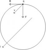
Using the drawing in the attachment, consider an infinitesimal element of the filament, which flows a current i (DC).
The magnetic field lines are circles, and the magnetic field B is tangential to these circles.
That is ! 😉
As an immediate consequence, the magnetic field B does not break the chaotic motion of the electrons produced by thermionic effect.
This result can be generalized to almost all forms of filaments used in valves.
"The cathode, heater, and surrounding apparatus, as a complex 3-dimensional structure" should be specifically designed to break the chaotic movement of electrons, as is the case of CRT's deflection yoke.
Q.E.D.😀😀
Attachments
Can you explain that, please."The cathode, heater, and surrounding apparatus, as a complex 3-dimensional structure" should be specifically designed to break the chaotic movement of electrons, as is the case of CRT's deflection yoke.
Q.E.D.😀😀
- Status
- Not open for further replies.
- Home
- Amplifiers
- Tubes / Valves
- Heaters & Filaments: AC vs. DC