Popilin and Junkie:
I think you've got the right idea, but one thing backwards:
If you want to drive away electrons from the heater,
and leave them available for tube current to plate,
then you want your heater more NEGATIVE, i.e.,
repelling the electrons and leaving them floating
in the vacuum ready for attraction to screen and plate.
Thus if the effect were purely electrical (electric field),
I would have to say you "float" your heaters (and entire D.C. supply) BELOW Ground, say about 50 volts!.
If they are separated from the Cathode electrically,
and you have a -ve Bias supply already, why not use it to
submerge your heaters -40 volts below ground?
But if the effect is in part magnetic (and lets see how this could come about🙂,
other solutions must be added.
We all know that D.C. current magnetizes many metals and alloys,
i.e., iron, steel, nickel, etc. and that both heaters and cathodes
are made of various materials.
It may be that in some tubes, either the heaters, or the cathodes (or both) can be magnetized.
If so, the next question is:
How or why would this magnetization affect the electron release and/or
the electron cloud?
Finally, could the original poster be mistaken or unclear in
his description of the phenomena?
Could he be referring to the well-known (or supposedly better understood)
polarization of the heater in a Directly heated cathode,
whereby bias (and current) is affected across the filament surface?
Always the same, I solve a problem you can not, and later, armed with the solution that I found, I am fiercely attacked.
This is very easy for you, I happened with other "opinionologyst" and critics by profession, here at the forum.
I do not know yours, but filaments that I know are NOT EQUIPOTENTIAL, so if you float at say
V(float) = V(k) +/- V(f)/2
(The +/- sign is for the DC filament power supply, if you connect the positive terminal to V(float) use + sign, if you connect the negative terminal to V(float) use - sign)
One end of the filament is at potential V (f) / 2 above the cathode potential, while the other end of the filament is at potential V (f) / 2 below the cathode potential, then the effect of the electric field between the cathode and the filament on the emitted electrons by thermionic effect is minimized.
I said it in simpler form in the post # 3, but have I also make to you the calculations?
I also hope that you remember that repel and attract the electrons produced at the cathode by thermionic effect is a job for the grid, and if you want, for the anode. AFAIK.
Magnetic field strength on a charged particle is of the form
F = q v x B
First, because the product vector, is tangential force, on the other hand we are talking about small speeds and fields, then its effect is almost negligible in the case we are concerned.
In the case of a permanent magnetization of the cathode, the interaction of the magnetic momentum is also negligible due to the chaotic movement of the electrons emitted by thermionic effect.
Do not make me do the math, that are complicated, and today is Sunday.
Best regards
Johann
Last edited:
Any current generates a magnetic field, both AC and DC. So an AC current generates an AC field. In addition, an AC voltage generates an AC magnetic field.
Since you trobbins forward in post # 6, and I apologized for my mistake in post # 7.
I also saved my error correctly, and with fundamentals.
What will you do? ashamed again?
On your website have a section where you talk about something we can not talk in the forum, apparently not much practices, right?
Best regards
Johann
Yes, I have seen that somewhere too; something to do with metal migration or electrochemistry. I have also seen it declared as nonsense. Does anyone know the truth on this? It sounds plausible. It could also be an audiophile myth.
Not certain whether it applies to audio sized valves, but TV transmitter finals' filaments are fed DC and incorporate an automatic polarity switch at (the rare) turn off-on's. The reason was explained to me as a valve life issue. Might be true...
A clever person on DIYAudio posted that the same could be accomplished in a stereo amplifier by wiring the two channels' valves in opposite polarity and switching between from time to time. True genius is simple, ain't it?
Thanks,
Chris
Always the same, I solve a problem you can not, and later, armed with the solution that I found, I am fiercely attacked.
This is very easy for you, I happened with other "opinionologyst" and critics by profession, here at the forum.
...who's attacking you?
Perhaps you have confused me with someone else?
If you think not, perhaps you can point to the post
where you think you were attacked.
While you're at it, why not point to the post
where you think you solved a problem,
which you also think I later claimed to have solved.
They must smoke a lot of drugs in Argentina.
I suggest you cut back a bit.
We were discussing the general picture,I do not know yours, but filaments that I know are NOT EQUIPOTENTIAL, so...
both filaments and heaters (for those who bother to nitpick about names,)
and both Direct and Indirect (i.e, heater/cathodes, and separate heaters and cathodes.),
and we were also talking about
BOTH D.C. and A.C..
So it is foolish to make generalizations about equipotential
(equal voltage potentials at different ends and at different times).
But go ahead, and then claim you're a genius.
Be my guest.
When you can write clear and concise English sentences,...
if you float at say
V(float) = V(k) +/- V(f)/2
(The +/- sign is for the DC filament power supply, if you connect the positive terminal to V(float) use + sign, if you connect the negative terminal to V(float) use - sign)
One end of the filament is at potential V (f) / 2 above the cathode potential, while the other end of the filament is at potential V (f) / 2 below the cathode potential, then the effect of the electric field between the cathode and the filament on the emitted electrons by thermionic effect is minimized.
I said it in simpler form in the post # 3, but have I also make to you the calculations?
I will then trust you to make correct and accurate calculations.
Both mathematics and English are international languages,
and you have to be expert at both to avoid sounding like a confused know-it-all.
Again, a coherent sentence would be a good start.I also hope that you remember that repel and attract the electrons
produced at the cathode by thermionic effect is a job for the grid,
and if you want, for the anode. AFAIK.
I presume you mean that you would like to limit the job of repelling and attracting electrons
to the grid and and plate (and we hope, the screen!).
However, any and all strategies dealing with hum,
must of necessity deal with re-direction of electrons involved with heater and cathode.
If you think otherwise, you are engaging in magical thinking.
But this is a discussion about strategies for dealing with issues surrounding the cathode and heater.
We are not just interested in your opinion about hum, but in many issues. Here are a few:
(1) Hum and noise injected into signal path and passed on to subsequent stages.
(2) longevity of the heater element.
(3) longevity of the cathode, especially those which have special coatings or surfaces.
(4) Grounding loops and other associated problems.
(5) D.C. potential of heaters in regard to other tube elements.
(6) things that affect cathode emission, and free electron motion.
Your claim/theory to have solved all the issues under discussion (2) longevity of the heater element.
(3) longevity of the cathode, especially those which have special coatings or surfaces.
(4) Grounding loops and other associated problems.
(5) D.C. potential of heaters in regard to other tube elements.
(6) things that affect cathode emission, and free electron motion.
is simply an embarrassment to all those of us
who wish to continue to discuss it.
This is still your own writing, as evidenced by the grammatical mistakes and clumsiness.Magnetic field strength on a charged particle is of the form
F = q v x B
First, because the product vector, is [a] tangential force,[;] on the other hand we are talking about small speeds and fields, [ - so] then its effect is almost negligible in the case we are concerned.
Moreover, its irrelevant.
One can only talk of a 'tangental force'
in relation to a previously specified direction.
You are unaware of what you are talking about.
Since the cathode, heater, and surrounding apparatus
is a complex 3-dimensional structure with multiple directions of possible electron paths, your point is worthless.
In the case of a permanent magnetization of the cathode, the interaction of the magnetic momentum is also negligible due to the chaotic movement of the electrons emitted by thermionic effect.
This is correct.
But since you are incapable of forming proper English sentences, this last perfect sentence has been cut and pasted from a book or webpage.
Don't worry, there is no danger of me "making you do the math."Do not make me do the math, that are complicated, and today is Sunday.
Best regards
Johann
As a physicist, I wouldn't trust you to do any math,
beyond letting you balance your rent payments,
having now seen this remarkable piece of performance art.
Please stop relying on Google-translate to help you,
and get an English teacher to review your work before posting.
Last edited:
I read somewhere that with dc supplies it's recommended to reverse the polarity from time to time. If I remember correctly, it was something to do with dissimilar metals and the like and deterioration at contacts. Anyhow, can't remember where I saw it (somewhere on the internet) but the recommendation was simply to reverse the polarity every once in awhile. I think the poster had some fancy scheme to auto-change direction at power up.
This is a very interesting point, and previously undiscussed.
It had not occurred to me, but you are correct in noting that
the cathode (and other elements) are often made of a different metal than the solid supporting connecting wires they are usually welded to.
I wouldn't be surprised that long-term unidirectional current flow could cause physical wear, pock-marks and eventual failure of a metal-to-metal connection.
I wish I had considered this before now.
It is something that can easily be investigated with a microscope and some old tubes of various types.
Of course electron flow in ANY direction ought to cause some wear and tear on welded connections, however it is quite feasible that constant flow in a single direction might do quicker erosion of joint materials.
I wonder if this could also be a factor in vacuum-seal failures around the wires which protrude from the glass.
Not certain whether it applies to audio sized valves, but TV transmitter finals' filaments are fed DC and incorporate an automatic polarity switch at (the rare) turn off-on's. The reason was explained to me as a valve life issue. Might be true...
A clever person on DIYAudio posted that the same could be accomplished in a stereo amplifier by wiring the two channels' valves in opposite polarity and switching between from time to time. True genius is simple, ain't it?
Thanks,
Chris
I'd have to see the circuit to confirm the effect is possible.
Anything that minimizes plugging in and unplugging connectors, could assist in failures due to contact-breaches.
Yes, I have seen that somewhere too; something to do with metal migration or electrochemistry. I have also seen it declared as nonsense. Does anyone know the truth on this? It sounds plausible. It could also be an audiophile myth.
In fact, the main mechanism of metal corrosion is actually electric in nature:
Fundamental of Corrosion Chemistry
DEFINITION OF METAL CORROSION.
Metal Corrosion can be defined as the destructive attack of a metal through interaction with its environment.
DRIVING FORCE FOR CORROSION.
Most metals used in the construction of facilities are subject to corrosion. This is due to the high energy content of the elements in metallic form. In nature, most metals are found in chemical combination with other elements. These metallic ores are refined by man and formed into metals and alloys. As the energy content of the metals and alloys is higher than that of their ores, chemical re-combination of the metals to form ore like compounds is a natural process.
FUNDAMENTAL MECHANISM OF ATTACK.
Corrosion of metals takes place through the action of electrochemical cells. Although this single mechanism is responsible, the corrosion can take many forms. Through an understanding of the electrochemical cell and how it can act to cause the various forms of corrosion, the natural tendency of metals to suffer corrosion can be overcome and equipment that is resistant to failure by corrosion can be designed.
The Electrochemical Cell.
As in all chemical reactions, corrosion reactions occur through an exchange of electrons. In electrochemical reactions, the electrons are produced by a chemical reaction, the oxidation, in one area, the anode, travel through a metallic path and are consumed through a different chemical reaction in another area, the cathode. In some cases, such as the common dry cell battery, electrochemical reactions can be used to supply useful amounts of electrical current. In marine corrosion, however, the most common result is the transformation of complex and expensive equipment to useless junk.
Components.
In order for electrochemical reactions to occur, four components must be present and active. These components are the anode, cathode, electron path, and electrolyte.
Anode.
In an electrochemical cell, the anode is the site where electrons are produced through the chemical activity of the metal. The anode is the area where metal loss occurs. The metal loses electrons and migrates from the metal surface through the environment. The electrons remain in the metal but are free to move about in response to voltage gradients.
Cathode.
The cathode in an electrochemical cell is the site where electrons are consumed. For each electron that is produced at an anodic site, an electron must be consumed at a cathodic site. No metal loss occurs at sites that are totally cathodic.
Electron Path.
In order for electrons to flow from the anodic sites to cathodic sites, the electrons migrate through a metallic path. This migration occurs due to a voltage difference between the anodic and cathodic reactions. Electrons can move easily only through metals and some non-metals such as graphite. Electrons from electrochemical reactions cannot move through insulating materials such as most plastics nor can they directly enter water or air. In some cases, the electron path is the corroding metal itself, in other cases, the electron path is through an external electrical path.
Electrolyte.
Electrolytes are solutions that can conduct electrical currents through the movement of charged chemical constituents called ions. Positive and negative ions are present in equal amounts. Positive ions tend to migrate away from anodic areas and toward cathodic areas. Negative ions tend to migrate away from cathodic areas and towards anodic areas.
Anodic Reactions.
Metal loss at anodic sites in an electrochemical cell occurs when the metal atoms give up one or more electrons and move into the electrolyte as positively charged ions.
Typical Reactions.
The generic chemical formula for this metal loss at anodic sites is:
where:M ---> M+ + e-
M = uncharged metal atom at the metal surface
M+ = positively charged metal ion in the electrolyte
e- = electron that remains in the metal
This type of chemical reaction is called oxidation even though it does not directly involve oxygen but only results in an increase in positive charge on the atom undergoing oxidation.
More than one electron can be lost in the reaction as in the case for iron where the most common anodic reaction is:
where:Fe --->Fe2++ 2e-
Fe = metallic iron
Fe2+= ferrous ion that carries a double positive charge
Correlation Between Current Flow and Weight Loss.
For each specific anodic reaction a characteristic number of electrons are produced in the reaction of one metal ions. Thus, all other things being equal, the metal loss is proportional to the number of electrons that are produced. As the electrons produced migrate to cathodic areas through the electron path, the metal loss is proportional to the current flow. In cases where more positively charged ions are produced, more electrons flow for a given number of corroding metal atoms but the current flow remains proportional to the metal loss.
Cathodic Reactions.
The electrons that are produced at anodic sites are consumed at cathodic sites. The type of chemical reactions that consume electrons are called reduction and have the generic chemical formula:
where:R+ + e- --> Ro
R+ = a positive ion in solution
e- = an electron in the metal
Ro = the reduced chemical
In reduction, the chemical being reduced gains electrons and its charge is made more negative. In some cases, where the ion in solution has a multiple positive charge, the total positive charge on the ion may not be neutralized. In other cases, the chemical which is reduced may not be a positive ion but is a neutral chemical which then becomes a negatively charged ion in solution in a reaction such as:
R + e- --> R-Source : "Corrosion Control" NAVFAC MO-307 September 1992
Hi nazaroo
In post post # 1 and # 2 you exhibited a problem, in post # 3, I gave a solution, in post # 8 you used my solution to criticize me, in post # 22 I tried to clear up your misconceptions, and now it turns out that for my terrible English I'm not your height.
I'm just a TV repairman, but if you are a physicist you hide it very well.
Best regards
Johann
Hi nazaroo
In post post # 1 and # 2 you exhibited a problem, in post # 3, I gave a solution,
Lets have a look:
The two problems posted in #1 and #2 (not one problem) were (are):
(1) Cathode emission inhibition caused by use of a DC heater supply.
(2) AC (electro-)magnetic field effects from large currents.
These two problems are actually totally independent. (2) AC (electro-)magnetic field effects from large currents.
I am the one who brought them together,
NOT because they are the same problem or have the same solution,
but because the typical solution to one was the apparent CAUSE of the other.
Now you made one irrelevant claim:
(1) "... from Maxwell's equations, we can see that the source of magnetic field due to AC is voltage, not current."
This is of course nonsense, because:
(a) Maxwell's equations do not make assertions about cause and effect, but only state relations between parameters (incorrectly in fact, because they don't take into account the velocity of electromagnetic radiation, or Newton's concept of Absolute Space. All this was replaced by Einstein's concept of a limit to the speed of light, and indeed all matter, and a the second idea of Space-time, in which the two form parts of a single geodesic field-structure.)
(b) It is well-known that limiting CURRENT minimizes electromagnetic fields, and also power losses, preventing contamination and making the most efficient form of power transfer and transmission. That is why all Hydro and Power grids use HIGH VOLTAGE and LOW CURRENT, to minimize bleeding of power through the electromagnetic field around wires and transformers.
Then you went on to state an entirely different problem, while calling it "the initial problem":
(1) "Returning to the initial problem, how to charge a cathode if it is at a potential close to zero if fixed bias is used?"
Ignoring the grammar, this was not the initial problem at all.
The two initial problems, again were:
(1) Cathode emission inhibition caused by use of a DC heater supply.
(2) AC (electro-)magnetic field effects from large currents.
Your 'solution' was actually a 'solution' to the problem of heater hum, which was not a solution at all to either of the problems stated.
Neither of your following statements actually even solved the "hum" problem, since your language was so confused that you failed to indicate whether you thought the voltage on the heater should be more negative or less negative than the cathode.
More annoying, you assumed "fixed bias is used",
when no such constraint was discussed.
If you had in fact solved the "hum" problem,
you would by your own words have only solved it for fixed bias topologies.
Well, if your post #3 is ambiguous, meaningless, garbled and in need of clarification,in post # 8 you used my solution to criticize me,
take it like a man.
Perhaps you too can be a physicist if you learn to listen more carefully,in post # 22 I tried to clear up your misconceptions, and now it turns out that for my terrible English I'm not your height.
I'm just a TV repairman, but if you are a physicist you hide it very well.
Best regards
Johann
and read more carefully, and actually follow the discussion.
I'm sorry to hear you are a TV repairman,
because that career hasn't been viable for nearly 30 years.
Also, those who did that job mostly died of cancer from the X-rays out of the back of TVs.
I'm surprised you're still alive.
Last edited:
This thread is rapidly descending into Alice in Wonderland territory. I will sit on the sidelines for a while and see if people recover their composure.
This thread is rapidly descending into Alice in Wonderland territory. I will sit on the sidelines for a while and see if people recover their composure.
That's to be expected when the initial quote was pulled straight out of the rabbit hole.
Is it me or is this thread getting a little too...heated? Sorry, couldn't resist.
resist? was that a pun?
This thread began with AC/DC, so I guess the dude look like a lady was no real surprise.
I hope speech impediments don't get traced to TV exposure.
An externally hosted image should be here but it was not working when we last tested it.
http://www.youtube.com/watch?v=kQFKtI6gn9Y

Last edited:
I suggest the issue relating to swapping the DC polarity is related to the contact interface between power supply and tube terminals, rather than any internal parts of the valve. And it may well be that heater tube terminals for such Tx types are substantially different from anything 'we' normally come across, and operate in a substantially different temperature environment and at different voltage levels. But worth eeking out some more background understanding.
Gentlemen (sorry to call them so, but still do not know)
I regret to say that I was mistaken when I thought I was wrong.
What I said in post # 3 is correct, I was wrong when I apologized in post # 7
I have checked my calculations and are correct.
Excuse the quality of attachments, were made with MathType, and the only way to upload that came to mind was this.
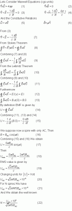
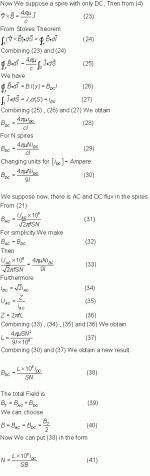
For an Ideal loop where an AC current i(AC) flows with a voltage U(AC), from equation (20), the AC magnetic field is given by
B(AC) = [ U(AC) x 10^8 ] / [ sqr (2) * (Pi) * S * f ]
Clearly only depends on the AC voltage, not AC current.
For an ideal loop where a DC current i(DC) flows with a voltage U(DC), from equation (28), the DC magnetic field is given by
B(DC) = [ 4 * (Pi) * u * i(DC) ] / ( c * l )
Clearly only depends on the DC current.
The confusion of some members of the forum, lies in the fact that whenever we have a current, we also have a voltage, and vice versa.
I regret to say that I was mistaken when I thought I was wrong.
What I said in post # 3 is correct, I was wrong when I apologized in post # 7
I have checked my calculations and are correct.
Excuse the quality of attachments, were made with MathType, and the only way to upload that came to mind was this.
For an Ideal loop where an AC current i(AC) flows with a voltage U(AC), from equation (20), the AC magnetic field is given by
B(AC) = [ U(AC) x 10^8 ] / [ sqr (2) * (Pi) * S * f ]
Clearly only depends on the AC voltage, not AC current.
For an ideal loop where a DC current i(DC) flows with a voltage U(DC), from equation (28), the DC magnetic field is given by
B(DC) = [ 4 * (Pi) * u * i(DC) ] / ( c * l )
Clearly only depends on the DC current.
The confusion of some members of the forum, lies in the fact that whenever we have a current, we also have a voltage, and vice versa.
Attachments
Not certain whether it applies to audio sized valves, but TV transmitter finals' filaments are fed DC and incorporate an automatic polarity switch at (the rare) turn off-on's. The reason was explained to me as a valve life issue. Might be true...
A clever person on DIYAudio posted that the same could be accomplished in a stereo amplifier by wiring the two channels' valves in opposite polarity and switching between from time to time. True genius is simple, ain't it?
Thanks,
Chris
Hi Chris
The valve that you refer, is directly heated cathode?
Best regards
Johann
Hi Chris
The valve that you refer, is directly heated cathode?
Yes, great big expensive things that are actually *rebuilt* when worn out. I doubt many stations still use electron valves - most, as I understand it, now use multiple paralleled solid-state amplifiers - but even ten years ago the big tungsten filaments still walked the Earth.
All good fortune,
Chris
Is it me or is this thread getting a little too...heated? Sorry, couldn't resist.
Only now I understand your joke. Genius!!! LOL
I think too slowly, right?
Best regards
Johann
Yes, great big expensive things that are actually *rebuilt* when worn out. I doubt many stations still use electron valves - most, as I understand it, now use multiple paralleled solid-state amplifiers - but even ten years ago the big tungsten filaments still walked the Earth.
All good fortune,
Chris
I think I know the cause of the reverse polarity of the filament / cathode.
If the filament/cathode is powered with DC, one half has less(more) emission than the other, and aging is uneven, so reversing the polarity happens the other way around.
Best regards
Johann
- Status
- Not open for further replies.
- Home
- Amplifiers
- Tubes / Valves
- Heaters & Filaments: AC vs. DC