The heater circuit must not be left floating, it should be referenced to common, or to a positive voltage to reduce coupled AC hum. The power tube's cathode (if cathode biased) sits at a positive potential.
But that's not the way to do it: the 6.3v AC center tap should be referenced, not one of the AC lines. If the power transformer 6.3v does not have a center tap, one can be made with two 100 ohm series resistors, and the reference will be taken between these two resistors.
But that's not the way to do it: the 6.3v AC center tap should be referenced, not one of the AC lines. If the power transformer 6.3v does not have a center tap, one can be made with two 100 ohm series resistors, and the reference will be taken between these two resistors.
Check out Dynaco ST35 schematic. The cathodes of output tubes are connected to the heaters directly.
Art
That's a great example.
Another possibility is a centertapped 6.3v but with a blocking cap on the CT.
heaters floating,headamp outputCheck out Dynaco ST35 schematic. The cathodes of output tubes are connected to the heaters directly.
Art
An externally hosted image should be here but it was not working when we last tested it.
You are all correct in the case of this circuit - there are two resistors across the transformer, but only for the heaters of the driver tubes, whereas the power tubes have the heaters connected to the cathode.
On another note, I can't work out how the driver section of the amp functions (it is a reverse engineering job as no schematic is available). The signal is sent through half a 6sn7 which has a plate voltage of 65v, then the plate has a wire link to the grid of the second half of the 6sn7, which in turn has a plate voltage of 130v before the signal is sent to the 6v6 tubes via 0.22uf capacitors.
I originally thought it was a cathodyne phase circuit, but the lower plate voltage of the 6sn7 is in fact on the input side of the amplifier. Any thoughts of what the topography might be?
You are all correct in the case of this circuit - there are two resistors across the transformer, but only for the heaters of the driver tubes, whereas the power tubes have the heaters connected to the cathode.
On another note, I can't work out how the driver section of the amp functions (it is a reverse engineering job as no schematic is available). The signal is sent through half a 6sn7 which has a plate voltage of 65v, then the plate has a wire link to the grid of the second half of the 6sn7, which in turn has a plate voltage of 130v before the signal is sent to the 6v6 tubes via 0.22uf capacitors.
I originally thought it was a cathodyne phase circuit, but the lower plate voltage of the 6sn7 is in fact on the input side of the amplifier. Any thoughts of what the topography might be?
Sounds like a directly coupled stage, with one half of the 6SN7 feeding the other, for increased gain. Rather low plate voltage for a 6SN7.
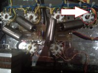
Whilst carrying out some modifications on a 6V6 amp, I noticed that on one of the tubes the heater (6.3V AC) is linked/soldered to the cathode. See attached pic.
What purpose does this serve?
I may be mistaken, but when I look at your photo I see the soldered joint between pin 1 and pin 2. Assuming I am correct, the cathode is not connected to the heater. Rather, pin 2 which is one of the heater pins is connected to pin 1. Pin 1 is a ground connection pin assignment for older metal 6V6 which most people have not likely encountered since most all later 6V6 varieties are glass. Many people have taken advantage of the typically unused pin 1 tab as another junction node for wiring purposes. In your case it looks like pin 1 is a ground point as when you follow the wires connected to pin 1 they all appear to connect to all pin 1's of the 6V6 tubes and you can also see one end of what looks like a 100k grid leak resistor connecting to each. Mickeystan.
Last edited:
Sounds like a directly coupled stage, with one half of the 6SN7 feeding the other, for increased gain. Rather low plate voltage for a 6SN7.
Brilliant! This has been driving me crazy. Is this a well known type of circuit? Any common schematics as examples? I think a re-wiring might be in order to fix the plate voltages.....
Brilliant! This has been driving me crazy. Is this a well known type of circuit? Any common schematics as examples? I think a re-wiring might be in order to fix the plate voltages.....
Yes, common. Often used in preamps to increase gain. Supratek Chenin preamps are an example, where they use a directly coupled 6SN7 as the gain stage.
- Status
- This old topic is closed. If you want to reopen this topic, contact a moderator using the "Report Post" button.
- Home
- Amplifiers
- Tubes / Valves
- heaters connected to cathode?!