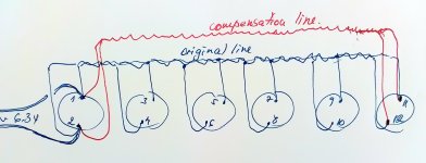
Hello. I have a fault in my power tubes heater wiring please. There are 6 tubes in line 6550 spaced around 12 inch from first to the last. A solid AWG 17 was used to do a twisted heaters line. The average curent from the first tube to the last one is 8A around. Still I recorded 35mV loss in one wire and 47mV in the other from the first tube to the last one (It was supposed to be identical but I used wires from two different batch from colour reason and are not identical for same length). Well... I know why I did it wrong now but because everything was well posed and built I looking for a quick solution to fix it. And the first thing was going through my mind is to run an additional twisted pair from the first tube directly to the last. I called it "compensation line" marked in red on my sketch. Please take a look on my drawing and let me know if it work please. Thanks.


Last edited:
I would make the heater connections only at the middle, and remove the other connection.
Symmetry is a good thing.
Daisy chain connection only works well for all low current filaments,
or else with the highest current filaments first in line.
Daisy chain connection only works well for all low current filaments,
or else with the highest current filaments first in line.
Have a look here. Tungsol recommends attaching opposite ends of the busbars to equalize current.https://frank.pocnet.net/sheets/127/6/6336A.pdf
Page 5- fig. 3
Page 5- fig. 3
Power the highest current tubes first in the chain, the sensitive signal tubes should be at the end. If they are all the same tubes/use, I suppose you could power them from the middle. I'm curious why are you worried about 47mv?
There are not sensitive tubes on this heaters rail. Is Power tubes only. I have another winding to feed the rest. Still the mctavish Tung Sol proposal looks interesting. Thanks.
There are 35mV in one wire 47mV in the other . Total 82mV wiring loses difference from the first tube to the last one please. I don't even know how much count... It was just a random measurement who shows my faulty design. The amp is not noisy or get tubes current issues at all. But if I catched it I want to try to fix it as much as I can...
Last edited:
Yes. It work as it should. Thank you.Have a look here. Tungsol recommends attaching opposite ends of the busbars to equalize current.https://frank.pocnet.net/sheets/127/6/6336A.pdf
Page 5- fig. 3
Last edited:
Excuse me I come again to my original question but I.m not a pro so I have some doubts...Despite the fact the voltages over each filament are well balanced In the supply wires neither the voltages and currents in each segment are equal, (except in the middle of the rail) ...So even well twisted they will not canceling in phase...So splitting at the middle as rayma suggested should be a better option please ? Thinking maybe not perfect voltage balanced but also effective canceling the emi fields...Thanks.
Last edited:
The heater filaments in each of the six tubes are not exact copies of each other. They have different hot and cold resistances by a minimal amount, nothing is perfect.
You are not “ canceling phase” when you twist the heater wires, you are simply REDUCING the amount of the radiated EM field.
The tiny differences that you’re dealing with do not make much change in the overall system. It’s like worrying about your car tires, three are 45 psi and the fourth one is 45.1 psi. Just doesn’t really matter that much……
I hope that helps👍🏻
Sorry, this arrangement only serves for proper current disribution, but opens a big disadvantage: There's a high AC current wiring loop of considerable area, prone to introduce massive hum into small signal stages. This issue has yet been discussed in the Heater Wiring thread here.Have a look here. Tungsol recommends attaching opposite ends of the busbars to equalize current.https://frank.pocnet.net/sheets/127/6/6336A.pdf
Page 5- fig. 3
Best regards!
Edit: See here!
This particular heater wiring is for the output stage (of 6 valves), where there are massive signal voltages and currents, and wouldn't (by design) be near small signal stages.
Yes. Supplied at opposite ends works perfect as well for me, without noticeable induced extra noise. I don't know if I may assume it as good heaters wiring practice or not. From my point distributed power from 2 separate lines right in the middle of group of 3 ( at socket 2 and 5)should be correct way to do it for such 10 A ac current. Well, I missed the point from beginning and did it wrong. But from a quick fix solution both works equally well in my design. Posing supply wiring outside chassis is unusual as well but was easiest quick compromise to supply correct the circuit because I didn't wanna mess with all wiring job already done.


Last edited:
You may assume it is😃I don't know if I may assume it as good heaters wiring practice or not.
The engineers who built the tubes originally were the ones who recommended this method. You have to realize that there is a really large amount of current involved here and small resistance's in the wires themselves play a role as well.
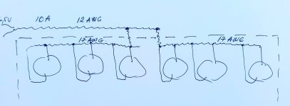
Current flow is equalized by having one phase on each end of the string of heaters opposite the other.
Look at your drawing above, how does the current flow?
Heater wiring located above the chassis is not common, but imho it is 'no issue'. I have seen it in an early 1950's custom amplifier.Posing supply wiring outside chassis is unusual as well but was easiest quick compromise to supply correct the circuit because I didn't wanna mess with all wiring job already done.
Of course the other wiring configuration that can be used is with multiple heater feeds to those six valves (eg. 2 pairs, 3 pairs or 6 pairs of heater feeds), with a star point near/at the power transformer.
It was already stated, and it is: the best current distribution is in the wiring scheme you suggested above. Some steel braided mesh sleeve or steel tube may be used to shield the lines. Thanks.Look at your drawing above, how does the current flow?
Last edited:
- Home
- Amplifiers
- Tubes / Valves
- Heater wiring problem
