I've been playing around with a voltage doubler as I have a pair of vu meters that require 12vac or 12vdc ish to drive them. I,m about to build a PP UL amp using 4 ecl86's
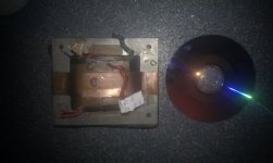
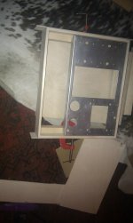
My power supply (attached photo) has a couple of thick green heater wires (top right) 6.3Vac
A couple of yellow wires (top left) 6.3Vac
It has a pair of thick red wires (bottom right) 5V for rectifier tube.
The amp I'm building also requires a - 7 V ish rectified DC...
Would really like some suggestions on how to go about supplying all the different voltages without underpowering the ecl86 heaters (which I beleive draw 700-mA) and also without compromising audio.
Is it unrealistic to think that the PSU green heaters wires could power all 4 heaters?
Or could I heat two tubes from the yellow and two from the green and then take a rectified - 7 v from one lot and approx 12vac or 12vdc from the other?
Anyone had any experience with this?
Attachments
Last edited:
If you're taking somebody else's word for those secondary voltages it wouldn't hurt to check them for yourself; that's not the usual color code. It's more likely to find 6.3 volts on the green pair, 5.0 volts on the yellow pair. Measurements without load can fool ya too.
All good fortune,
Chris
All good fortune,
Chris
Thanks Chris, I will check the greens! I've been playing with the yellows already tonight and they were approx 7.75 unloaded, I built an amateur (noob) voltage doubler and got 19Vdc from them unloaded...
It still does not answer my question of what topology I may think about for my PSU...
P.s. the thick reds are definatley 5V as they were connected to GZ34 in old amp, the rest of the heaters were split between the greens and the yellows. The greens had an exrtra tube connected to them too...
cheers Stuart
Oh, well there you go. Based on the size of that critter you ought to be able to power a half dozen or so of those amplifiers.
All good fortune,
Chris
All good fortune,
Chris
Do you know how I'd go about utilising the heater supplies for:
.................approx 12Vdc/ac for vu meter driver
.................approx -7 Vdc for ccs
and of course.... 4 ecl86 heaters?
.................approx 12Vdc/ac for vu meter driver
.................approx -7 Vdc for ccs
and of course.... 4 ecl86 heaters?
Last edited:
Without knowing anything about it, I'd keep the 12 volts for the VU meters floating. Maybe make it from the 5 volt winding with a doubler. You have two reasonably heavy duty 6.3 volt windings for the ECL86's, no problemo.
The -7 VDC could be made from the remaining heater winding, or as a "back voltage" by lifting the negative connection from the B+ supply and reconnecting through a 7 volt Zener.
If you have it to spare of course. What are your B+ plans so far?
All good fortune,
Chris
The -7 VDC could be made from the remaining heater winding, or as a "back voltage" by lifting the negative connection from the B+ supply and reconnecting through a 7 volt Zener.
If you have it to spare of course. What are your B+ plans so far?
All good fortune,
Chris
Thanks Chris, food for thought - to be honest, i'm still noobing around.. I'm sure i can build this amp but I'm on a sttep learning curve... My B+ is still unconfigured, spent a night with PSUD2, I want to rectify by tube GZ34 or 5R4
By floating I understand this means a supply from a secondary that is not referenced to ground? I presume if I use a GZ34 in standard full wave rectification then I can no longer use its 5V heater supply to feed into a doubler for 12Vdc?
As far as a 'back voltage' by lifting the negative from the B+ is concerned - I will have to learn how to do this... it sounds complicated right now!
maybe i'm a little out of my depth...
Stuart
My B+ is still unconfigured, spent a night with PSUD2, I want to rectify by tube GZ34 or 5R4
By floating I understand this means a supply from a secondary that is not referenced to ground? I presume if I use a GZ34 in standard full wave rectification then I can no longer use its 5V heater supply to feed into a doubler for 12Vdc?
As far as a 'back voltage' by lifting the negative from the B+ is concerned - I will have to learn how to do this... it sounds complicated right now!
Yes, the GZ34 will need the 5.0 volt winding all to itself. But you have lots of windings. IIRC one red pair is 6.3 volts? I think the 12 volts needs to be floating because the circuit can accept AC or DC power. This probably means a full wave bridge in line. No biggie for you anyway.
I'm sorry I can't explain the back voltage thing better. Maybe imagine borrowing 7 volts from the *bottom* of the power supply. The remaining B+ stays above ground and the 7 volts goes "below" ground. If your supply was originally 300 volts, you'd have 293 volts B+ left, and the Zener would have to pass all of the current that went through the B+ too.
You'll be great, and have fun,
Chris
hmm, does this mean the whole amps B+ floats 7 V above ground? I'm trying to get my head around this...
OK, let's try another way. (I'm sorry I'm not better at this). Imagine the B+ supply to be a 300 Volt battery, so that it's easy to imagine it floating. Now we connect the normal amplifier load and a 7 Volt Zener in series, across the big battery. Doesn't matter where we tie this contraption to chassis, it'll work the same, dividing the 300 Volts between the normal amplifier load and the 7 Volt Zener.
Now lets connect the junction of the NAL and the 7VZ to chassis ground. If we measure with our voltmeter from chassis to top (+) of the battery we measure +293 Volts, and if we measure from chassis to the other end (-) of the battery we measure -7 Volts.
Our rectified AC supply can be just like that battery, with its (-) end "floating" just like its (+) end conventionally does. Make sense? Sorry I'm not clearer.
All good fortune,
Chris
Btw, please remove both the resistors 470R and the 1K pot called 'balance' from the tail of your PI. They're simple unnecessary.
Best regards!
Best regards!
Thanks Chris and Ray too....
So, B+ (vie tube rectification and filter caps etc) goes to amp as normal?
Center Tap has the zener diode in series whereby: transformer side = -7V and the the other side makes the 0V for the amp?
This is how I'm imagining it, I could be completely wrong!
Will the Zener put any interference into my B+? Does the 0V eventually go to ground after passing the output stage of the amp? I know my CT was connected to ground via a 500mA fuse on the amp I took the PSU from.
Thanks ever so much for all your help Chris, as you can probably tell, I'm still a little confused! You have pushed me on leaps with the confidence to build this and, don't worry, I will not be wirring anything up until I fully understand how it works!
If taking the -7V becomes complicated or compromises safety/audio then I do have a schematic to take the negative V for ccs from a 6.3V rectified heater supply. But then I would have to put a small 9Vac transformer in the amp to seperatley power the VU Meter driver unit.
Stu
Stuart,
As long as you don't overload an ENTIRE transformer then overloading a single winding by anything up to about 50% usually doesn't matter too much.
I would:
Use the High Voltage Windings and the 5V winding for your tube rectifier as "standard"
Use one of the 6.3V windings (one with finer wire if they are not the same size wire) into the voltage doubler which will give you approx. +16V (give or take a volt) and then run a 12V regulator IC off that for your 12V supply
Use the second 6.3V winding to provide all 4 ECL86 heaters, also connect a bridge recifier across the winding connected to the 2 AC connections, connect the +Ve output to 0V and you will find that the -ve output will be around -7V, use this for the 2 CCS supplies. They only drawaround 1.5mA each (3 mA total) so a 100uF/16V electrolytic cap would be fine. Put a 100nF low voltage polypropylene across it too. The voltage (-7V) isn't actually that critical.
Yell if you want me to draw a sketch of the circuit for you.
The origimnal amp in the schematic had a voltage doubler High Voltage power supply with 60uF/900V polypropylene filter caps. It sounded just stunning. Having built a Baby Huey based System for all of my neices one of my sisters (mother of 2 of the nieces) said "what about me" so she now has this amp driving some Polk Audio speakers and with an vintage Marantz preamp.
Cheers,
Ian
Last edited:
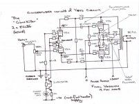
Hi Ian, I didn't get back to you sooner because I wanted to be able to draw you a diagram of how I thought it would go... however, I couldn't quite picture it, so a diagram of the heater 6.3Vac and the bridge for the ccs would be great when you have a moment.
I presume I drop the IEC mains inlet ground to chassis as soon as it enters the amp. I then have the CT from the 270- 0 -270Vac winding for the GZ34 recitifer, I would normally fix this to the chassis with a fuse? I think what you are describing is running the CT (0V) all the way through audio section and dropping to ground at the end of the 0V bus?
In which case does the 0V from the 6.3Vac bridge join with the CT to run through the amp?
and.... you mention a 900V Voltage doubler on the HT which uses a 60uf cap to ground in the final stage of smoothing, however the schematic that I'm looking at states 300V HT and yet the capacitor is there! Can I use a lesser capacitor if I'm using 300V HT?
Stuart
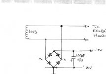
Gotta watch those diode polarities, but the plan looks great.
Thanks,
Chris
You sure as hell do - take 2 (with diode polarities corrected)
Cheers,
Ian
Attachments
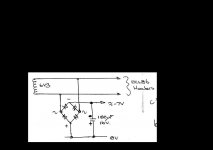
Lovely, that is what I imagined it to look like - thanks for the confidence boost
Would you run the 0V through the amp and ground it after it had been past the PI?
And stick the HT winding CT to ground through fuse imediatley or join it to 0V line from your diagram?
Almost there! Just ordered 4 PIO K40Y-9 0.1uf 400V capacitors and I'm learning how to finish wood very quickly to insert my metal chassis!
and for Ian....
Can you tell me if the schematic I'm following is fine for 300V HT and therefore can I scap the 60uf 900V cap for a lower voltage one?
cheers in advance...
Attachments
Can anyone tell me if the 0V from the recitifed 6.3Vac as shown above goes on to eventually be grounded at the chassis? I'm confused as I would normally connect the CT from the high voltage secondary windings of my transformer to ground and this would also make the 0V for the B+
cheers in advance, Stuart
cheers in advance, Stuart
- Status
- Not open for further replies.
- Home
- Amplifiers
- Tubes / Valves
- heater currents