I'm trying to resuscitate an early-60s Bell T-338 reel-to-reel with an integrated RP-320 preamp. In the course of the inspection prior to replacing the electrolytics, I noticed that the heater wiring for the two 12AX7/12AT7 pairs differs from the published schematic.
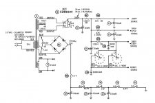
The heaters are driven by a 24V winding from the main transformer. This feeds a Selenium bridge type rectifier. The output of the rectifier goes to a 4.7Ω resistor, then splits. One leg goes to a 150 mfd cap (one section of a can; all 150mfd caps are in this can), the other to the heater of the first tube. This is where the actual wiring departs from the schematic (both circuits shown in attachments; V1 and V3 are 12AT7, V2 and V4 are 12AX7).
On the schematic, the 4 tubes are wired in series, with the heaters on each tube in parallel (voltage to pins 4 and 5, out pin 9). The sequence is 12AT7: 150mdf to ground : 12AT7 : 150mfd to ground : 12AX7 : 12AX7 : ground.
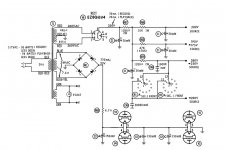
The preamp is wired with two tube pairs in series (the two tubes in each pair are in parallel). The heater on each tube is wired in series (in pin 4, out pin 5, pin 9 not used). The sequence is 12AT7/12AT7 : 150 mfd to ground : 150 mfd to ground : 12AX7/12AX7 :ground. Yes, there are two caps in parallel between the two tube pairs.
Since this whole thing is driven by replacing the caps, I'm curious about having two caps in parallel between the two pairs. In particular, I'd like to know if this was a matter of expedience (using the existing component) or if there is a valid reason for using 300mfd instead of some other value. Or more to the point (since the can is being replaced and I can do what I want), should I consider some other value for all three of these caps?
As an aside, the transformer has a 24V .250A winding which is used only to drive these 4 heaters and a separate 6.3V 1.2A winding which is used only to drive the heaters on a 6V4 and 12AU7 and an indicator light. This seems an unusual transformer (at least, I can't find a replacement with 520V, 24V, and 6.3V secondaries). Is there a reason for running the 12AX7 and 12AT7 heaters on DC? Is there a reason for not using one 6.3V source (rectified and/or not) to drive all 6 heaters?
Thanks.
The heaters are driven by a 24V winding from the main transformer. This feeds a Selenium bridge type rectifier. The output of the rectifier goes to a 4.7Ω resistor, then splits. One leg goes to a 150 mfd cap (one section of a can; all 150mfd caps are in this can), the other to the heater of the first tube. This is where the actual wiring departs from the schematic (both circuits shown in attachments; V1 and V3 are 12AT7, V2 and V4 are 12AX7).
On the schematic, the 4 tubes are wired in series, with the heaters on each tube in parallel (voltage to pins 4 and 5, out pin 9). The sequence is 12AT7: 150mdf to ground : 12AT7 : 150mfd to ground : 12AX7 : 12AX7 : ground.
The preamp is wired with two tube pairs in series (the two tubes in each pair are in parallel). The heater on each tube is wired in series (in pin 4, out pin 5, pin 9 not used). The sequence is 12AT7/12AT7 : 150 mfd to ground : 150 mfd to ground : 12AX7/12AX7 :ground. Yes, there are two caps in parallel between the two tube pairs.
Since this whole thing is driven by replacing the caps, I'm curious about having two caps in parallel between the two pairs. In particular, I'd like to know if this was a matter of expedience (using the existing component) or if there is a valid reason for using 300mfd instead of some other value. Or more to the point (since the can is being replaced and I can do what I want), should I consider some other value for all three of these caps?
As an aside, the transformer has a 24V .250A winding which is used only to drive these 4 heaters and a separate 6.3V 1.2A winding which is used only to drive the heaters on a 6V4 and 12AU7 and an indicator light. This seems an unusual transformer (at least, I can't find a replacement with 520V, 24V, and 6.3V secondaries). Is there a reason for running the 12AX7 and 12AT7 heaters on DC? Is there a reason for not using one 6.3V source (rectified and/or not) to drive all 6 heaters?
Thanks.
Attachments
I would replace the selenium rectifier assembly (which will be weak and drop too much voltage)
with 1N4005 silicon diodes, and increase the value of the series 4.7 ohm resistor to get the correct
filament voltage. It will have to be significantly higher in both ohm value and wattage (use a 5W).
The tubes with DC operated heaters are likely input stage tubes that would be more sensitive to hum.
There's nothing special about the paralleled capacitors, just replace them with the same or higher
capacitance and voltage ratings. If possible, when replacing double the capacitance and the
voltage rating for each part. The more the better, and try to use high ripple current types.
But do check when finished for the proper filament voltages being present.
Last edited:
I'm guessing that running the heaters at 11V was intentional, as this seems to be not uncommon in that era, especially for low current applications.
The schematic indicates that the rectifier drops 1V. Dunno if that's accurate or not, as I want to replace the caps and do a little more inspection before powering it up. In any event, getting 12.6V from a 24V winding would require both a rather large resistor and rewiring the circuit to run all 4 tubes in parallel (since it's not clear how get the 25.2V required to keep the current layout with the heaters in series).
Am I missing something?
Just keep the circuit topology as it is, replace the capacitors, and verify proper voltages.
Then you can (if desired) replace the selenium rectifier with silicon diodes,
and replace the 4.7 ohm resistor with a larger value/wattage to restore the
correct voltage on the filaments. You could likely even increase the filament voltages
to 12.6VDC by choosing the proper replacement value of the 4.7 ohm resistor.
Last edited:
How would one keep the topology and increase the filament voltages to 12.6V? The transformer secondary puts out 24V. If the topology stays the same, there are two tubes in series, each requiring 12.6V if run at full voltage; that's 25.2V, correct? How would one go from a 24V output to a 25.2V input?
The original schematic may well have provided the least ripple voltage on the heaters to V1, V3. But the 'as wired' schematic provides redundancy of operation if a tube is pulled or a heater circuit opens (although remaining tube heater voltages may increase a bit).
Operating the heater from DCV attenuates a couple of sources of hum that may eek their way in to the signal path at the front end. V1 and V3 are likely to be the first preamp stages, and so their gain exacerbates any hum ingress, and hence they get the better hum filtering (think of the filtering as a CRC filter with the middle R being the V2 - V4 heater).
The selenium rectifier would be subtly better than a silicon pn diode (even with added R) for commutation noise, however that would be offset by using modern replacement filter caps. If you are replacing a multi-section can with separate caps, then you may be able to achieve lower commutation noise by wiring the new caps so as not to include common chassis current path - that may be a bit tricky to understand, and may be easier to explain if you include a photo or 2.
I'd recommend keeping the existing heater wiring circuit. For safety against pulling tubes, make sure the new caps are at least 35V rated, as all caps could have 34Vdc on them and that could be a titch higher due to mains voltage.
Last edited:
What do you want pictures of? It's a rat's net in there. ")
I'm not sure what you mean by "common chassis current path". Do you mean to suggest grounding all caps at the same point? The existing can has a dedicated ground wire running to who-knows-where (not the transformer); I can't see where the chassis connection is made.
I'm mainly curious about the values of the new caps. All three sections in the can are rated at 150mfd, 25V. If a 150mfd is adequate for the initial reservoir cap (is it?), what's optimal for the filter cap that sits between the AT7s and AX7s? I haven't found either 150mfd or 300mfd caps to exactly dupe the original components, so it looks like I either put two caps (e.g. 100 and 50) in parallel to keep the original values, or change the values to some thing better and/or readily available. The way I figure it, if I have to change something, I might as well change it for the better.
I get why they're running these heaters on DC -- I just don't understand why they would they would use what seems (to me, anyway) to be an unusual transformer rather than running all heaters off the same winding. Assuming the 6.3V secondary has sufficient current to drive all 6 tubes, why not run the 6V4 and 12AU7 heaters off 6.3VAC and the 12AX7 and 12AT7 off rectified DC from the same winding?
The capacitor values are not at all critical, they just have to be large enough to reduce the
ripple to the desired level. Larger is better.
Lower load current for a transformer (series filaments) means thinner, cheaper wire, and also
cheaper, smaller, lower uF capacitors.
ripple to the desired level. Larger is better.
Lower load current for a transformer (series filaments) means thinner, cheaper wire, and also
cheaper, smaller, lower uF capacitors.
Last edited:
The lower current requirement of the 24V supply may be related to the selenium rectifier parts available at the time, and their PIV voltage and load current capabilities. A 6.3Vdc supply wouldn't have been capable of generating from a 6.3Vac winding back in those days due to diode drop, and the need for a physically larger stack than there is room for. What is a concern is that selenium diodes age, and so they should be replaced rather than retained.
I'm with rayma that cap value is not critical, and I'd suggest even 100uF (or 200 or 220uF) instead of 150uF is fine and would come down to what you can easily get (but I recommend 35V caps), and that you are unlikely to notice any hum difference unless you have the right measurement tools.
My comment about 'common chassis current path' is that that is the default situation with a can cap, as you appreciate. The first filter cap should connect its neg terminal directly to the diode bridge neg terminal, and cap neg terminal taken to the V2/V4 chassis gnd point. The neg of the next filter caps should preferably be at the V1/V3 chassis gnd. Also preferably keep the diode bridge and wiring and dropper resistor away from V1-V4 to avoid capacitive coupling of any ACV on parts/wiring over to input grids.
Last edited:
Thanks for your help.
V1, V3, the can, and the rectifier are all grounded at the same point (one lead from the rectifier to the can, a second lead from V3 to V1 to the can to the stereo 1/4" monitor jack). V2 and V4 heaters have no direct chassis ground, as their heaters connect to V1 and V3.
Is it sufficient to replace the three can sections with two 100uF sections (one before V2/V4, one between V1/V3)? It seems that there are slim picking for something 200/220uf rated 35V or above; everything seems to be either low-budget generic caps or as big as the existing can.
Ahh sorry about the V2/V4 error. My comment should just have said:
The diode bridge neg terminal should connect to the filter cap neg terminals directly, and the cap neg terminals taken to the V1/V3 chassis gnd point.
And you indicate that is the situation, so no issue from me.
You can use PSUD2 to indicate the ripple voltages when using 100uF for each section, and it is about 9Vpp with the cap experiencing 260mA ripple, which may get close to ripple limit for some caps. The V1/V3 then have 2.5Vpp ripple on them. That may be noticeable given it is twice mains frequency.
When using 2x100uF for each section, the first cap has 6Vpp with 300mA ripple (now managed by 2 caps). The V1/V3 then have about 0.8Vpp ripple on them. That may be acceptable in comparison to what was in place.
Last edited:
Thanks for all your help on this.
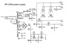
As it turns out, what I've got is some bastardized hybrid version of this preamp. It was apparently built when they were moving to an updated design. For example, the heater wiring has the new topology (e.g. pairs of parallel tubes in series rather than 4 tubes in series), while the two 150 uF can sections that are in parallel are spec'd as a single 500 uF can section in the update.
It was apparently easier to use a chassis that was already half-built rather than starting over from scratch..
As it turns out, what I've got is some bastardized hybrid version of this preamp. It was apparently built when they were moving to an updated design. For example, the heater wiring has the new topology (e.g. pairs of parallel tubes in series rather than 4 tubes in series), while the two 150 uF can sections that are in parallel are spec'd as a single 500 uF can section in the update.
It was apparently easier to use a chassis that was already half-built rather than starting over from scratch.
.I would do the following:
- Replace the selenium rectifier by a silicon bridge or four separate Si diodes, as yet suggested.
- Replace the 1st filter capacitor by a 220 µF 35 V electrolytic.
- Replace both 2nd ones by a 220 µF 35 V also.
- Adjust R68 to get not more than 25.2 Vdc at the 1st filter capacitor when the tubes are fully warmed up.
Best regards!
Plan is to make a bridge rectifier from 4 1N4005s. I used glass passivated (1N4005GP-E3/54) because of the higher heat rating.I would do the following:
- Replace the selenium rectifier by a silicon bridge or four separate Si diodes, as yet suggested.
Do you mean replace the two parallel caps with two 220 µF caps (effectively making a 440 µF cap) or replace the two sections with a single 220 µF? FWIW, the updated design (see attached schematic) specs the first cap at 150 µF and the second at 500 µF.- Replace the 1st filter capacitor by a 220 µF 35 V electrolytic.
- Replace both 2nd ones by a 220 µF 35 V also.
The transformer secondary is spec'd at 24V. The schematic allocates 1V loss across the selenium rectifier and the 4.7Ω R68/R161 drops that to 22V (because they presumably want to run the heaters at 11 V). I'm not trying to be stupid here, but how do I get 25.2V from a 24V secondary?- Adjust R68 to get not more than 25.2 Vdc at the 1st filter capacitor when the tubes are fully warmed up.
Is there anything magic about 11V? I realize that was done back in the day in low-demand applications, but if the rectifier output is 23V, why not dispense with R68 and run the heaters at 11.5V? Why not dispense with it now and run them at whatever full output from the silicon bridge turns out to be?
Attachments
Manufacturers often found that input stage noise levels could be lowered by using a lower heater voltage. The disadvantage is the tube performance/life can suffer as it is lower than 12.6 - 10%. So it was a conscious decision then, and can be now!
That doesn't mean the 2nd stage valves have to operate with the same concern as the input stage - both for lower DCV and/or for lower ripple voltage. It also doesn't mean that the DCV has to be 11V, and couldn't just as easily be whatever is nominal (although it shouldn't be over 12.6+5%). It may be easier for the amp owner to test screen each input stage valve for lowest noise and then use that as a way to optimise their amps performance if they were so inclined.
That doesn't mean the 2nd stage valves have to operate with the same concern as the input stage - both for lower DCV and/or for lower ripple voltage. It also doesn't mean that the DCV has to be 11V, and couldn't just as easily be whatever is nominal (although it shouldn't be over 12.6+5%). It may be easier for the amp owner to test screen each input stage valve for lowest noise and then use that as a way to optimise their amps performance if they were so inclined.
They are astonishingly "equivalent". Which confirms the notion that if your budget for uFd and Ohms has not changed, you should get the same result.
I simmed both but only captured the first because there is so little difference.
300uFd was a LOT in those days. This is not clean DC on all tubes, only the end pair. Which is logically the lowest-level stages in the box, probably mike preamp and head preamp. The ripple here is 1/3 Volt with very low upper overtones (low buzz).
11V was VERY widely used on 12AX7 and kin working at less than datasheet conditions. Even lower has been used when working at super low plate current. Several of the ills of hot cathodes are less when less-hot.
This thing has been fine for many years. Don't fret about solved problems.
I do agree on the Selenium. When it goes bad, the stink clears the house. You'll get a tenth-volt back with fresh Silicon. And new caps are a great excuse for old Selenium to throw a fit and burn its guts.
Attachments
Yes, Konga Man, I should have been more clearly, as I'd recommend you to buy two 220 µF 'lytics and replace either the 1st and the 2nd one(s) by just one of them. If there's ample space, you could also increase the capacitance if you want.
Rectifying 24 Vac by a diode bridge into a reservoir capacitor leads to a idle DC voltage that calculates to 24 V*sqrt2 - 2*VF. Assuming a diode forward voltage of 0.7 V you'll get 32.5 Vdc. Hence, there should be some headroom to adjust the heater voltage by a suitable R68.
Best regards!
Rectifying 24 Vac by a diode bridge into a reservoir capacitor leads to a idle DC voltage that calculates to 24 V*sqrt2 - 2*VF. Assuming a diode forward voltage of 0.7 V you'll get 32.5 Vdc. Hence, there should be some headroom to adjust the heater voltage by a suitable R68.
Best regards!
Yeah, I got that AC RMS peak value after I thought about it for a couple of seconds. You apparently can't edit old posts, so my brain cramp will live for eternity.
FWIW, the selenium rectifier seems to be working fine. It's going anyway.
The transformer seems to run high, though. I was running it at 11.7V (10% of spec'd input) with my hillbilly variac (Lionel train transformer; use what ya got) and all the tubes pulled. The secondaries measured 26.2V, 28.7V, 2.68V, and .68V. Assuming linear extrapolation (which may not be a valid assumption), that's 262V, 287V, 26.8V, and 6.8V from the secondaries with 117V input. It's spec'd at 260V, 260V, 24V, and 6.3V, respectively. If those readings hold at full voltage with all the tubes in (i.e. under operating conditions), is it advisable to add resistors to the other outputs to bring the voltage down to where is should be? The 6.3V output runs the heaters on a 12AU7 and 6V4. The 260V outputs feed the plates on the same 6V4.
Hayseed sez they can build a 150µF/500µF can (i.e. spec values) for the heater circuit. I'm not wild about dropping $35 on it, but there's not much room underneath and two separate caps would (IMHO) present a less than optimal appearance up top. I'd guess I could bump that first section up to 220µF without a problem.
150µF electrolytics are not hard to come by. I had my first go recently at hollowing out some can caps and 'stuffing' them. They were both '48 vintage 16uF + 16uF 500VDC cans, and the new 500VDC/105C rated, low ESR, long life 16uF radials just rattle inside there. Even if appearance is not an issue, there is some extra real estate for bulky caps inside the can, and the solder lugs are normally integral to the wiring.
As an aside, has anyone else noticed that there are suddenly lots of 500V electrolytics to choose from, due to new LED light implementations? They used to be special, and pricey, but now they are priced proportionally to other voltages.
As an aside, has anyone else noticed that there are suddenly lots of 500V electrolytics to choose from, due to new LED light implementations? They used to be special, and pricey, but now they are priced proportionally to other voltages.
Attachments
- Status
- This old topic is closed. If you want to reopen this topic, contact a moderator using the "Report Post" button.
- Home
- Amplifiers
- Tubes / Valves
- Heater circuit on Bell RP-320 preamp