I noticed in the F6 build guide that the recommended heat sink size is 25 square inches per device or more. Is measuring the size of the fins what I need to do to determine the size? I.E. I have a pair of heat sinks with 22 fins each at 2" x 1.75" that I would like to use. So is 22 x 3.5 =77 square inches the right way to figure the size for the 25 sq inch rule of thumb?
Thanks,
Marty
Thanks,
Marty
Have a look at the 4U chasis in the store, does yours match that?
No it is smaller with deeper fins
Few things. The mounting plate thickness, black anodizing and if the fins are serrated (wavy) all add to the efficiency of the heat sink. Also the fins should be vertical. Also, mount the mosfets toward the bottom of the heat sink, not the top third of the heat sink.
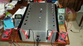
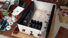
My F6 uses 2- 1.25" x 6" x 8", black anodized, non-serrated heat sinks per channel. Back plate is .25" thick.
At the required bias, the heat sinks do not get uncomfortably hot to the touch. In warmer weather they can get very hot, but still within the hand/time test.
My F6 uses 2- 1.25" x 6" x 8", black anodized, non-serrated heat sinks per channel. Back plate is .25" thick.
At the required bias, the heat sinks do not get uncomfortably hot to the touch. In warmer weather they can get very hot, but still within the hand/time test.
Attachments
Last edited:
No, not really. Fin spacing and count plays a part too. It's all about surface area.
My way is not scientific, so I will get pooped on, but what I do is take the volume of the heat sinks as I will use them (in pairs, side by side) and make sure the fins have a good number count and are not ridiculously spaced apart.
Take for example the XA-25 heat sinks. Not very big, but if you take all the surface area and count it up, it's a pretty big heat sink.
I don't like this term, because of where it comes from, but the real only "rule of thumb" when it comes to heat sink is you can never have too m much heat sink.
With math set aside, that's the best way to do it.
Another approach would be to start with full power on and start with 0 bias voltage.
Bring up the amp bias gradually until it starts to heat up. Taking note as to how hot it's getting. Try to get to the recommended bias.
A better, safer way is to use a variac to bring up AC slowly, monitor bias voltage across the source resistor, adjust the bias so that it doesn't go over the required bias. All the while, looking for over-heating parts or smoke. If you see smoke, back off and ID the part that's problematic. Check your soldering/wiring/parts placement with AC off and filter banks discharged.
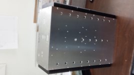
Send us a pic o the HS and maybe have a ruler in front of it as a reference.
My way is not scientific, so I will get pooped on, but what I do is take the volume of the heat sinks as I will use them (in pairs, side by side) and make sure the fins have a good number count and are not ridiculously spaced apart.
Take for example the XA-25 heat sinks. Not very big, but if you take all the surface area and count it up, it's a pretty big heat sink.
I don't like this term, because of where it comes from, but the real only "rule of thumb" when it comes to heat sink is you can never have too m much heat sink.
With math set aside, that's the best way to do it.
Another approach would be to start with full power on and start with 0 bias voltage.
Bring up the amp bias gradually until it starts to heat up. Taking note as to how hot it's getting. Try to get to the recommended bias.
A better, safer way is to use a variac to bring up AC slowly, monitor bias voltage across the source resistor, adjust the bias so that it doesn't go over the required bias. All the while, looking for over-heating parts or smoke. If you see smoke, back off and ID the part that's problematic. Check your soldering/wiring/parts placement with AC off and filter banks discharged.
Send us a pic o the HS and maybe have a ruler in front of it as a reference.
http://sound.whsites.net/heatsink.zip
Is a spreadsheet that'll give you a pretty good idea. Give it a play and you'll get a feel for heatsinking.
Edit: hat tip to ESP audio and Rod Elliots excellent collection of articles
Is a spreadsheet that'll give you a pretty good idea. Give it a play and you'll get a feel for heatsinking.
Edit: hat tip to ESP audio and Rod Elliots excellent collection of articles
Last edited:
On the flip side, over been running an F5 at about 1amp bias and ~20V rails on a 80*50*300 mm heatsink for ages and she's warm, but not offensively so. There's definitely a level of comfort element to this descision, and the way I saw it, I've at least half a dozen amps about, so I'll just use the F5 in winter... ")
- Status
- This old topic is closed. If you want to reopen this topic, contact a moderator using the "Report Post" button.
- Home
- Amplifiers
- Pass Labs
- Heat sink size Q