Wade Stewart
Stewart Electronics
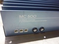
And some pics I've found of various MC500's.
Note the early ones seem to have a split heatsink and chassis bolted together.
EDIT;
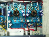
Cory, going by your photo, I'd say that is one of the early versions as it has the 'thumb wheel' adjusters for bias and dc offset.
Don't suppose you could upload some more pics of this poor unit ?
EDIT 2;
From the various pics it looks like Corys unit is a very early version (split heatsink) and that the MC500's do run 494's
Stewart Electronics
And some pics I've found of various MC500's.
Note the early ones seem to have a split heatsink and chassis bolted together.
EDIT;
Cory, going by your photo, I'd say that is one of the early versions as it has the 'thumb wheel' adjusters for bias and dc offset.
Don't suppose you could upload some more pics of this poor unit ?
EDIT 2;
From the various pics it looks like Corys unit is a very early version (split heatsink) and that the MC500's do run 494's
Attachments
Last edited by a moderator:
 email removed as requested
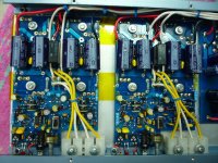
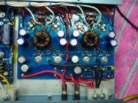
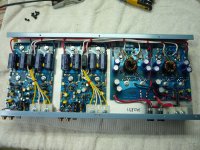
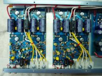
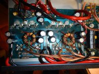
 It's nice to see a non-mutilated amp. This amp of mine was repaired several times 'before' me, cause it kept burning out. I am kind of embarrassed to show mine... It was "hot-rodded" with Phoenix Gold wire. And new filtering caps. All double in capacitance. Rev A was the power supply board and Rev B for the 2 output power boards.
On a side note. What fuse size is supposed to be for the power supply? The repair guy before me wrote max 5 amps. I see every other size bigger than this.
Also, since the power supply is kinda working. I put the fuses into the high voltage slots. After several minutes the furthest side popped the 5 amp fuses... Both boards have all new output transistors. Maybe there is a small transistor burnt out on the top of the board? Nothing shows any signs of problems...
Attachments
Just to clarify, those aren't mine.
I'm going through I guess its a midlife crises ?
I've bought several SS amps lately (D100ii MC245 MC300) and I want more")
So I've been hunting and collecting photos etc as I find them.
There have been 2 MC500's on evilbay recently.
One that I'm guessing is first version (same as yours) and a later version one.
But I don't have that sort of money (nor do I need that sort of power)..
Lets face it, these are now 30+ years old.
Chances of finding unmolested ones is slim, even though I managed to luck out with mine
My own deductions is SS increased fuse ratings as the revisions went along.
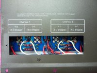
From the pics I posted, I believe the early one (yours) is meant to have 10amp fuses (internal).
Whereas the later version has 15amp fuses (internal).
The only external pic I have is of the later version and it shows 2x 30 amp for the main power fuses.
As far as I'm concerned, no need to be embarrassed as your doing your best to bring a loved one back to health
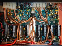
Edit, re the caps, I've seen a few where the 1,000uf have been replaced with 2,200uf.
once you look at the schematics of a few of these, they use a mix of 1,000uf and 2,200uf depending on location.
Personally I'd stick with 2,200uf through out otherwise you'd possibly risk overloading the power supply.
It might be ok to go higher, but I'd rather not invoke issues, especially when you have a reasonable amount of work to pull it apart for repairs.
I'm going through I guess its a midlife crises ?
I've bought several SS amps lately (D100ii MC245 MC300) and I want more
So I've been hunting and collecting photos etc as I find them.
There have been 2 MC500's on evilbay recently.
One that I'm guessing is first version (same as yours) and a later version one.
But I don't have that sort of money (nor do I need that sort of power)..
Lets face it, these are now 30+ years old.
Chances of finding unmolested ones is slim, even though I managed to luck out with mine
My own deductions is SS increased fuse ratings as the revisions went along.
From the pics I posted, I believe the early one (yours) is meant to have 10amp fuses (internal).
Whereas the later version has 15amp fuses (internal).
The only external pic I have is of the later version and it shows 2x 30 amp for the main power fuses.
As far as I'm concerned, no need to be embarrassed as your doing your best to bring a loved one back to health
Edit, re the caps, I've seen a few where the 1,000uf have been replaced with 2,200uf.
once you look at the schematics of a few of these, they use a mix of 1,000uf and 2,200uf depending on location.
Personally I'd stick with 2,200uf through out otherwise you'd possibly risk overloading the power supply.
It might be ok to go higher, but I'd rather not invoke issues, especially when you have a reasonable amount of work to pull it apart for repairs.
Attachments
Last edited:

I just wanted to give a great "thank you" to Perry Babin and Old 'n' Cranky for your input on this project. I know Perry helps a lot of people out, he helped me awhile back on a project. 
Perry, do you think that the larger caps in my power supply is causing the weird heat issue? From my knowledge, it shouldn't, but, its nice to hear different opinions...
Perry, do you think that the larger caps in my power supply is causing the weird heat issue? From my knowledge, it shouldn't, but, its nice to hear different opinions...
The magnetic materials are pretty stable and most can take very high temperatures but it is possible that they have degraded. I've seen it with inductors but never with a power transformer.
What is the operating frequency on pin 9 of the 494?
Look at the end of the email address and go to the website if there is one.
What is the operating frequency on pin 9 of the 494?
Look at the end of the email address and go to the website if there is one.
Wayne replied back:
Hello Cory,
Well I wish you had spoken to me about the fet's earlier. I recommend IRF3205SPbF. These are 110 amp fets. You can buy them at Mouser Electronics if you wish. The fet's that you replaced them with should work fine though. If you use the IRF3205's you will need to change the gate resistors from 47 ohm 1/4 W to 10 ohm 1/4 W. This i do to the higher gate capacitance. Your IRFZ44's the gate capacitance is actually 1/2 of the input capacitance of the 50N05. With such a low gate capacitance you might need to increase the gate resistors to about 100 ohms each to slow down the turn on.The only way to know for sure is to try it.
Do you have a scope and a generator? If so if you look at either side of the transformer secondary you should see a square wave at about 5t0KHz. If tere are small spikes at the leading edge. If this is more than 10 volts or so this is a sign of cross conduction. Meaning that both fet's are on for a short period of time This will heat them up very quickly. It may also heat up the transformer. I'm assuming by toroids you mean the transformers.
As for the fuses 15 amp is fine.
The Positive Voltage from the supply is always connected to the amp boards. the fuses connect the Negative Voltage to the amp circuitry.
Did you ask him if he had a diagram?
If you email him again, ask him about the deadtime (is the value you read from pin 4-7 what it should be)?
Without deadtime programed in (via pin 4), I don't see how this circuit can work, especially with the high 150 ohm pulldown and the high frequency (50kHz).
The Alpine MRV-1507 has a roughly similar drive circuit and without modification, it won't work with the 3205s.
- Status
- This old topic is closed. If you want to reopen this topic, contact a moderator using the "Report Post" button.
- Home
- General Interest
- Car Audio
- heat problem: changed MPT50N05E to IFRZ44PBE