How about two of these...
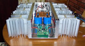
How about two of these per channel for an Aleph 2?
L*W*H = 300*300*40 (mm)
Thermal resis. 0.29 C/W
You can find them at www.rs-components.com
Product number 264-670.
Price each £58.85 (ex vat)
/loovet
How about two of these per channel for an Aleph 2?
L*W*H = 300*300*40 (mm)
Thermal resis. 0.29 C/W
You can find them at www.rs-components.com
Product number 264-670.
Price each £58.85 (ex vat)
/loovet
An externally hosted image should be here but it was not working when we last tested it.
This is a copy from, http://www.passlabs.com/pdf/xa-white-paper.pdf: "Their massive heat sinks run at about 25 degrees C above ambient temperature, so that actual chip temperatures are about 70 degrees below their rating."
If we know the values of C/W, W and ambient temperature, we could calculate the heat sink temerature approximately like this: Heat sink C = C/W x Watt + ambient temperature. Your temperature and size of heat sinks are yours.
Enjoy.
JH
If we know the values of C/W, W and ambient temperature, we could calculate the heat sink temerature approximately like this: Heat sink C = C/W x Watt + ambient temperature. Your temperature and size of heat sinks are yours.
Enjoy.
JH
I would just say that my own estimate of heatsink requirements is that they should be 2500-3300 in^2 for one channel of an Aleph 2. That's assuming that you manage to spread the devices around on it (them) and that they are no taller than about 10-12 inches. 2.54cm=1inch.
That's without figuring in the area of the back-side of the sink.
This is based upon lots of reading of what others have done and the results they have gotten, NP's own comments and my estimate of the surface area of the heatsinks on the commercial product, and his comments in response to questions like this. Also, my own experience with a Zen 4 and scaling it for the dissipation of an Aleph 2.
loovet,
2 x 0.29 °K/W = 0,145°K/W. For a 30°C rise you can burn 30/0,145=207watts.
This isn´t enough for an Aleph2 wich dissipates about 300 watts. What you need is an Rth below 30/300=0.1°K/W
william
2 x 0.29 °K/W = 0,145°K/W. For a 30°C rise you can burn 30/0,145=207watts.
This isn´t enough for an Aleph2 wich dissipates about 300 watts. What you need is an Rth below 30/300=0.1°K/W
william
wuffwaff said:loovet,
2 x 0.29 °K/W = 0,145°K/W. For a 30°C rise you can burn 30/0,145=207watts.
This isn´t enough for an Aleph2 wich dissipates about 300 watts. What you need is an Rth below 30/300=0.1°K/W
william
Thanks william
I will have to look around for another one. But it's not that easy to find those heatsinks with high capacity, at least not for a reasonable price.
Are there any good places in Germany to shop heatsinks?
/loovet
Correction!!
These fans, Papst 8412NGL , ARE very silent - if you mount them correct. I made mistake to mount them inside "cages", which cause alot of "wind noise" not from fan itself but from air being sucked through holes in cage. Apologies to "Mr. Papst" - if there is somebody called that I also dropped the fan supply to just 10Volt, which made them virtually completely noiseless.
JDeV said:Actually I thought everything over again, did some calculations and decided (after reconcidering your comments) to reconnect the fans, but replacing the existing "out of old PC powersupplie" 1's with the highly aclaimed (and highly
Papst 8412NGL fans. ...BTW - these new fans are not really much an improvement on the noise issue, IMO 🙁 Expected much more for $30 worth of fan.
These fans, Papst 8412NGL , ARE very silent - if you mount them correct. I made mistake to mount them inside "cages", which cause alot of "wind noise" not from fan itself but from air being sucked through holes in cage. Apologies to "Mr. Papst" - if there is somebody called that
I also dropped the fan supply to just 10Volt, which made them virtually completely noiseless.heat issues with SoZ 
Is the use of Peltier effect thermoelectric cooling devices OK? Has anybody given this any consideration?
Vic
Is the use of Peltier effect thermoelectric cooling devices OK? Has anybody given this any consideration?
Vic
Peltier effect devices aren't really "cooling" devices. They are better thought of as solid state heat pumps. They actually add more heat to the system, and will make your heatsinks a LOT hotter. Depending on your heatsinking setup, they may or may not reduce the Tj of the power transistors, but the extra 12VDC power supply, along with the cost of the peltier devices would be better spent on heatsinks in almost all cases.
Thanks for the reply. I was just thinking of ways to get the heat away from the Mosfet. But your point is well taken. Furthermore, I can see that if the themoelectric device failed you'd get a meltdown.
Just thought I'd ask. I'm planning on building a SoZ amp and BoSoZ preamp (separately) and was trying to look for ways to keep the amp's size down. But, I guess size matters.
Thanks,
Vic
Just thought I'd ask. I'm planning on building a SoZ amp and BoSoZ preamp (separately) and was trying to look for ways to keep the amp's size down. But, I guess size matters.
Thanks,
Vic
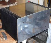
I used 6 of the MM5061-6 heatsinks on each of my 2's. My calculations come out to about 600 watts of dissipation give or take, and these beasts do run quite cool for sitting at .65 volts of drop on the source resistors. I reccomend these as they dissipate the heat very well, only thing is a bit more effort to construct the chassis.n With the panels in place each amp weighs in at 68 lbs!! Each sink cost me $25.00 from MM Metals which I thought quite reasonable. About $320.00 with shipping...wait was long though...about 10 weeks.
Mark
Mark
Attachments
Vic-
If you want to keep the amp small and move the heat somewhere else, here's a way:
http://www.diyaudio.com/forums/showthread.php?postid=145167#post145167
I know that this works. I used to build high-temperature industrial ceramics kilns, and the highest temp ones needed water cooling to protect the seal between the kiln and kiln car. We had to get rid of lots more heat than anybody will ever talk about in electronic applications, and we used to buy water-to-air heat exchanger units to do the job. They were very simple though, not something we couldn't diy on a small scale.
Water cooling was something I concidered for a while. My Idea was to put one of those wall of water decorative things on top of the stereo cabinet to dissapate the heat. It would add a lot of humidity to the air, but we people on the Gulf Coast run A/C all the time anyway. Instead I bought 8 feet of extrusion from MMMetals. My monoblocks can easily dissapate 500 watts at 60 deg C before the fan. ( tested one of 4 sinks with 4 150 ohm 50W sinkable resistors with 70 volts each)
Attachments
heatsinks for dummies
this thread has been very informative, for me. i want to make sure i really understand some stuff in my pursuit of
😱 The Ultimate Frugalphile Penultimate Zen Amplifier 😱
🙄
so here's my take: the standard zen4 amp needs a heatsink rated 0.3°C/W, per channel. for one channel, there are 3 transistors to mount on the heatsink. being still in the lower part of the electronics learning curve, i'm not sure how to calculate the watt dissipation per transistor, but i'm guessing it's not evenly divided among the three. however there's only three of them, so let's say i spread them out to get maximum heatsinking per component.
does that mean i can use a heatsink with a lower rating than 0.3°C/W? i mean, i could theoretically use 3 separate heatsinks rated at 0.9°C/W, could i not? (assuming equal wattage distribution for a moment.) if so, does that mean i could use the equivalent length extrusion of a 0.9 sink * 3?
what is the best way to spread components out on a heatsink? assuming vertically oriented fins, is it preferable to have a horizontal spread of components?
/andrew
hot topic
Thanks above for your replies.
I think I will avoid the water route since where I plan to put my amp is not situated for that type of set up.
I think that I'll bite the bullet and get a lot of heat sinks. This is my first amp project (SOZ) so it will be a learning experience. I like working with the mechanical aspects anyway and I am very new to the electronics stuff so it will be a fun project. It is part of my obsessive nature to research something to death before starting. I did make a pair of 2-way speakers a few years ago utilizing Audax drivers. The outcome was far better than what I expected. I think that the amp/preamp will suit them exceptionally well. I don't require a lot of power.
As I said the electronics stuff is new to me. In fact, after a month of looking at the SOZ amp, I finally figured out how the thing actually works. It came to me while I was stuck in traffic. (OK so I'm a little slow 🙄 .
I plan to work my way up the ladder.
Thanks again,
Vic
PS you guys out there sure know your @#%&
here's a specific question. MECI has a pretty good heatsink here.
according to aavid's profile, this extrusion has a Rth of 0.28°C/W.
using the logic i outlined earlier, let's say i want to mount ALL SIX transistors of a 2-channel zenv4 amp on a single extrusion. roughly speaking, if i spread them out equally each component gets 4" of heatsink.
a 4" portion of the same extrusion comes out to 0.69°C/W Rth.
this would seem to work fine. a required 0.3°C/W max rating for 1 channel results in 0.9°C/W max per transistor, unless i am mistaken. i'm hoping someone will correct me if i am...
i would very much like this to work...30 bucks for a heatsink for a stereo zenv4 would be a giant leap in my frugalphile quest.
any and all comments appreciated!
/andrew
front of devices
Hi,
Has anyone ever tried attatching an extra heatsink or l-shape extrusion to the front of the devices as well as the rear mounting area? It should help lower the device temprature somewhat without needing a massive surface area on the main heatsink only.
Thanks
Raj
Hi,
Has anyone ever tried attatching an extra heatsink or l-shape extrusion to the front of the devices as well as the rear mounting area? It should help lower the device temprature somewhat without needing a massive surface area on the main heatsink only.
Thanks
Raj
I have been considering "sandwiching" the Mosfet between two heatsinks. I am planning a SOZ amp. I haven't figured out how to adequately utilize heatsinking without making monstrous amps. According to my calculations;
working temp = 50C,
50 = C/W * W + ambient temp (say 20)
At 50 watts power output, 1200 watts dissipation.
C/W=.025.
I don't know how to do this with conventional heat sinking.
If I am wrong on my calculations, someone please correct me.
Thanks,
vic
working temp = 50C,
50 = C/W * W + ambient temp (say 20)
At 50 watts power output, 1200 watts dissipation.
C/W=.025.
I don't know how to do this with conventional heat sinking.
If I am wrong on my calculations, someone please correct me.
Thanks,
vic
faustian bargin said:[B...a 4" portion of the same extrusion comes out to 0.69°C/W Rth.
this would seem to work fine. a required 0.3°C/W max rating for 1 channel results in 0.9°C/W max per transistor, unless i am mistaken. i'm hoping someone will correct me if i am...
any and all comments appreciated!
/andrew [/B]
I can't confirm all of that, but I can tell you this much:
Be aware that the FET in the regulator portion dissipates only about 12W if I remember correctly. So most of the dissipation is across the other two transistors, and they do about 90W altogether, so plan accordingly.
I have built this amp, and I used some used heatsinks that I just picked up. I don't have the actual rating of them available, but they are about 825 in.^2 for each of the two main transistors, and it operates at 50C. That's with a length of about 5 inches. If your length varies much from something like that, you must adjust your figures to account, as heatsinks get less efficient as they get longer. (see the application notes on Aavid's page). Your figuring of 50C target and 20 degree ambient is good, but for safety you might want to figure an ambient of 25.
Good luck-
- Status
- Not open for further replies.
- Home
- Amplifiers
- Pass Labs
- heat issues