Thanks JensH.
The designer hasnt published the schematic though it is likely close to whats in the datasheet. I think it does have an output resistor. But your comments are valuable and I will pursue that.
Voltwide, thanks. i was hoping to tap the signal at the amplifier output and see on audacity. Dont have the right probes to feed to soundcard.
But yeah i might just analyze the recorded audio on audacity, though it probably has other recording crud.
that is what audacity reads from this file
Which file is that?
I think these files were LP at 300Hz with LR4,
so the 5Khz peak looks suspicious.
Am i reading this right?
Last edited:
It is 20160920_090609.mp4
Best is you check yourself - install audacity (open source) on your win/mac/linux machine and import the file.
It is really simple like that.😉
Yes, there is some peak around 5kHz
Best is you check yourself - install audacity (open source) on your win/mac/linux machine and import the file.
It is really simple like that.😉
Am i reading this right?
Yes, there is some peak around 5kHz
thanks voltwide. I will investigate some with audacity.
So as Jens suggested this is likely some marginal stability issue in the IV stages loaded by the balanced cable and the hypex amp inputs. I will suggest this direction to the designer who is investigating but is unable to recreate at his end.
So as Jens suggested this is likely some marginal stability issue in the IV stages loaded by the balanced cable and the hypex amp inputs. I will suggest this direction to the designer who is investigating but is unable to recreate at his end.
I have a suspicion that this could be some marginal stability.
It could be caused by the capacitive load of the inputs of the power amp + the capacitance of the cables.
I wonder if there is a series resistor on the output of the I/V stage?
Are there any added capacitors on the inputs of the power amps?
Op-amps and other amplifiers generally don't like capacitive loads directly on the output.
There are no additional capacitors to the amp input. Just a balanced mogami cable going through the required 4 Neutrik balanced connectors.
thanks voltwide. I will investigate some with audacity.
So as Jens suggested this is likely some marginal stability issue in the IV stages loaded by the balanced cable and the hypex amp inputs. I will suggest this direction to the designer who is investigating but is unable to recreate at his end.
I imagine the I/V stage is very similar to the data sheet example from ESS which is stable even with AD797 op-amps which can be prone to instability in the wrong circuit.
The Hypex amps use a fairly standard instrumentation amp arrangement of op-amps as a differential receiver, from memory they are AC coupled but they are not unusual in any way.
I think you need to do some basic tests with the DAC to make sure that it is working properly first. Run some tests of the output of the DAC back into your soundcard to see what you are getting. Try noise to give you the frequency response and then test tones to see if they are clean throughout the range.
I would use those tests to analyse rather than the one from your phone as who knows what sort of audio issues the phone recording may have had. If the frequency response straight out of the DAC with the DSP filter in place looks like the phone response then there is an issue as you should have almost nothing above 1000Hz at all with a 24dB filter at 300Hz.
If you want to check the wiring you could use the single ended (unbalanced) output from your DAC with an unbalanced to balanced cable as shown on the Hypex website. This will give you a baseline to make sure that there is no issue from the differential circuits. I use my Hypex amps with this wiring scheme and they work without issue.
Yes fluid, the plan is to do more investigations. As i mentioned, the DAC is currently with the designer and he insists that he isnt able to reproduce the issues.
The recording video is the closest i have come to capturing the issue. there could be recording related artifacts, but the issue is also captured.
The idea voltwide suggested is pretty nice for that investigation. The plot clearly shows high freq content and something even triggering the driver's cone ringing around 5KHz.
Also wanted to add that the NC400 is DC coupled
OK, it will be hard to test the DAC if you don't have it with you anymore!
May I suggest that you use one of the interfaces that work correctly and run the same test on one of those so you have a baseline to compare to? The audacity frequency spectrum does not look like a 300Hz 24dB filter so it would be useful to know what the output of your DSP is supposed to look like.
May I suggest that you use one of the interfaces that work correctly and run the same test on one of those so you have a baseline to compare to? The audacity frequency spectrum does not look like a 300Hz 24dB filter so it would be useful to know what the output of your DSP is supposed to look like.
Thanks fluid. Will post updates once i get the DAC back.
received the DAC back.
If anything the situation seems to have gotten worse.
The designer maintains that he sees nothing wrong on his end.
I dont really have an oscilloscope. A focurite 2i2 which doesnt seem to measure great is what i have at my disposal.
20170115_235557.mp4 - Google Drive
So the DAC has 4 IV boards.
Analog ground on these boards goes to the XLR connector through a balanced cable's shield and connects to pin 1 and chassis.
So there are a total of eight points where the analog ground connects to the chassis through shield of the balanced cable going to the output XLR connectors.
From what i read, balanced interconnect shield needs to connect to chassis at the pin 1 of the XLR, but analog ground should ideally connect to chassis at a different point.
Experts please comment.
Not an expert but AES standard has pin 1 only connected to the chassis and nowhere else. A differential signal isn't referenced to ground.
This document from Hypex explains the issue and I think Bruno Putzeys would count as an expert.
https://www.hypex.nl/img/upload/doc/an_wp/AN_Legacy_pin_1_problems.pdf
Papers by Bill Whitlock are also very good to read to understand grounding.
This type of issue would manifest as a ground loop or ground induced hum, i don't think that is your issue but it is always good to have things wired correctly.
Run some tests yourself to see what the output of each channel is when given a noise signal. This will show if there is an inherent problem. Compare against your other interface to see if there is a difference.
Thanks Fluid. I had read the hypex paper. Thanks for pointer to Bill Whilocks paper. I am going to invest in an oscilloscope.
I had done some investigations with an oscilloscope.
Posted some updates on the NCORE page.
http://www.diyaudio.com/forums/class-d/302602-ncore-diy-2.html#post4965322
http://www.diyaudio.com/forums/class-d/302602-ncore-diy-3.html#post4971894
I had done some investigations with an oscilloscope.
Posted some updates on the NCORE page.
http://www.diyaudio.com/forums/class-d/302602-ncore-diy-2.html#post4965322
http://www.diyaudio.com/forums/class-d/302602-ncore-diy-3.html#post4971894
From what I read on the other page you have too much signal coming out of the DAC so you are having to use a lot of attenuation from the digital volume control which is reducing signal to noise and resolution.
The simplest way to reduce output is to use the single ended outputs rather than the balanced. The balanced could be putting out up to 6V where the single ended is likely to be closer to 2V at full scale.
By using a single ended to balanced cable to the Hypex you get a lot of the common noise rejection with lower signal voltage.
It is easy to create an attenuator if you need to, you can create a potential divider with two resistors this can even be hidden inside the cable especially with an XLR plug. Use 1% or 0.1% tolerance resistors and the matching will be very high.
The UCD amps can have the gain changed by just one resistor but it is a fairly small smd one on the bottom of the board. Hypex are very helpful and will give you that information if you ask.
Thanks Fluid.
I am using the unbalanced output from the DAC. The distortions are less audible now, but still present.
I am reluctant to reduce the gain on the amp modules as that will be hard to reverse.
Yet i want to wrap my head around
1. Whats the real noise floor on my DAC outputs
2. Why does the noise appear to modulate with the music
3. What nominal rms voltage should be on the DAC output for good S/N on the amp input, and to operate the AMP at its lowest distortion wattage
4. I want to make sure for nominal home listening level, the DAC output level is where it performs the best and drives the AMP according to #3 above
I am not sure if reducing the gain on the amp modules will get me there.
1. That depends on how much digital attenuation you are having to use.
2. No idea.
3. You won't need much voltage to the UCD's if your speakers are efficient.
With music I can use a 1V output and still get my LX521 speakers to fairly
uncomfortable levels with UCD amps.
4. I would say between 1 and 1.5V would be enough.
Reducing the gain on the amps or using inline attenuators will help. I'm afraid that you will probably have to run some tests to confirm how much reduction you need.
What is the voltage that comes out of your other interface that works well? Does it have an analogue volume control?
Have you been able to try the DAC with a headphone amp or other passive speaker to confirm that it works as expected with those?
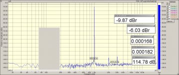
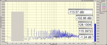
I got an RTX audio analyzer by JensH.
Got some measurements on the DAC.
please take a look
DIY Audio Analyzer with AK5397/AK5394A and AK4490
Got some measurements on the DAC.
please take a look
DIY Audio Analyzer with AK5397/AK5394A and AK4490
Put a scope on the output of the dac, it should give you more info. I've used a bunch of Motu gear (ES9016) with NC400s, and there's a bunch of ticking and other noise that becomes apparent. I never determined the exact cause, but likely related to the noise and dc offset from the interface.
Keep in mind, this is the same output:
Interface looks very clean.

Scope shows otherwise, high freq noise pulses and dc offset.

zoomed

This is what it sounds like when hooked up to a compression driver with a bunch of padding
motu 16a noise - YouTube
Keep in mind, this is the same output:
Interface looks very clean.
Scope shows otherwise, high freq noise pulses and dc offset.
zoomed
This is what it sounds like when hooked up to a compression driver with a bunch of padding
motu 16a noise - YouTube
Last edited:
Thank nyt for the detailed post and the video sample.
In fact our setups match very closely. I was initially using a Motu828mk3 interface along with NC400 and UCD400 amp modules in my 4way active setup. Later i moved to a custom 8CH es9018 DAC.
The above scope plots is exactly what i saw on my scope as well. But what i hear as described in this thread seems to be different.
adding the measurements to this thread as well.
Attachments

I never even bothered running normal audio signal like you did through a woofer. once I heard that idle noise I stopped there. I figured there might have been some kind of switching overlap/interference
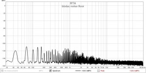
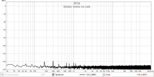
btw why is this not showing up in the fft spectrum? or is it the 70khz component seen in the plot?
any thoughts on the strange USB related noise grass?
any thoughts on the strange USB related noise grass?
- Status
- Not open for further replies.
- Home
- Source & Line
- Digital Line Level
- Hearing strange distortions