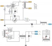
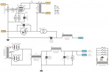
Hi guys, just wanted to run past my design for a tube headphone amp. It is a combination of Andrea's design (here) and the design here. See attached schematic.
Would appreciate and comments/feedback. It has been designed so that a 5842/C3g can be used instead, as they have a similar operating point, and all one needs to do is to use a switch (and different sockets obviously) to switch our R3.
There isn't anything ground breaking here. Just a combination of a few people's design, and my first attempt in designing and understanding tube circuits. Any insights, comments and feedback welcomed!
Attachments
Connect the earth end of the 0D3 to the top of the cathode resistors instead of earth and reduce their parallel value to 47 ohms to get the same bias point.
Last edited:
I read that on the elf website, but trying to understand the advantages of that beyond removal of the cathode resistor. Does it take the cathode resistor out of the signal path?
Epc no elf. Darn iPhone spell check.
ecp 😉
The idea of trying the regulator to the cathode is that it simplifies the signal current loop and keeps the cathode bypass cap out.
I would also actually recommend using a solid state shunt element instead of the OD3 -- the Zout of the OD3 is ~300R which I found detrimental to the circuit. A MOSFET can be less than an ohm. And, you can use the OD3 to bias the FET if you want to keep the neat glow.
Headphones especially Denons and Grados can pick up the slightest hum so you may not like the AC heat, I would at a miniumum elevate it +20V's. I would also caution 120hz buzz with sensitive phones with the small filtering you show, but it may be OK. You may want to try the Salas HV Shunt regulator. I just finished a WE417A SET headamp powered by the SSHV and it is incredible, others have similiar reports with the C3g + SSHV.
Did you see ecp.cc ?
With your schematic and the one above the CCS feeding two tubes will present sort of a push-pull situation rather than shunt + SET (which is what I think you want?) I always wanted to build this and see its behavior with a scope but never had the time, I'm just afraid the two tubes will play tug of war without the 2H cancellation.
dsavitsk posted at the same time, One other thing is oscillation with the 5842/C3g/6C45p. With the 5842 you want to try a grid stopper on all four grid inputs ( I used 10k) and a cathode stopper (5R) and a plate stopper (1R). Cut the socket pins down and solder the stoppers directly on the pins.
others have similiar reports with the C3g + SSHV.
Just a combination of a few people's design
That seems to refer to me...😀
Like the use of two halfwave rectifiers in the psu and Os-con in the cathode... a good sounding alternative to LED's...
I looks fine as it is, others have already given good advice (and I second regal on the SSHV regulator... very musical!)
🙂
Would like to keep the entire design simple by using just. A VR tube. But will look into the MOSFET regulator option proposed.
Regal, am interested in how the two tubes form a push pull pair. As far as I can see the bias resistor as it is shown now will force 18mA through the D3a. The balance will be through the 0D3. Unless the bias point of the D3a changes, which I assume over time as the tube age rather the over a very short period, the currents should remain unchanged. However, if the cathode resistor is to be common to both Tubes I can see how that will cause the two tubes to become a 'push pull' where the bias of the D3a will change as the two tubes are tied together.
Regal, am interested in how the two tubes form a push pull pair. As far as I can see the bias resistor as it is shown now will force 18mA through the D3a. The balance will be through the 0D3. Unless the bias point of the D3a changes, which I assume over time as the tube age rather the over a very short period, the currents should remain unchanged. However, if the cathode resistor is to be common to both Tubes I can see how that will cause the two tubes to become a 'push pull' where the bias of the D3a will change as the two tubes are tied together.
Regal,
Noted about lifting the heater voltage to 20~25V. Will check the tables to see the maximum limits. But you still think that I need more filtering? LCLC followed by a CCS and a VR? I thought that'd be plenty? No prob to add another LC stage.
Noted about lifting the heater voltage to 20~25V. Will check the tables to see the maximum limits. But you still think that I need more filtering? LCLC followed by a CCS and a VR? I thought that'd be plenty? No prob to add another LC stage.
Would like to keep the entire design simple by using just. A VR tube. But will look into the MOSFET regulator option proposed.
Regal, am interested in how the two tubes form a push pull pair. As far as I can see the bias resistor as it is shown now will force 18mA through the D3a. The balance will be through the 0D3. Unless the bias point of the D3a changes, which I assume over time as the tube age rather the over a very short period, the currents should remain unchanged. However, if the cathode resistor is to be common to both Tubes I can see how that will cause the two tubes to become a 'push pull' where the bias of the D3a will change as the two tubes are tied together.
I don't know, it just seems that you have a constant current driven, no matter where or what the cathode bias is I don't see what would hold the plate voltage with either tube. With a single CCS on two tubes it would seem the AC music signal would affect both tubes and cause a plate voltage swing on each of them. It is certainly an interesting circuit to try.
As far as filtering it really depends on your headphones, high ohm medium sensitivity probably OK, just if you plug in a set of Grados and hear buzz then think about the filtering, just wanted you to know it is a possibility to watch for. It is best to keep filtering to a minimum to keep the PS output impedance low, so you may need a little trial and error.
To be honest when I first plugged in my Grados when I finished building the SSHV-WE417A I expected to hear a little buzz or hum as most every tube amp does this with Grados, I was very surprised to hear a completely black background first time with the amp. Also I put the power supply/prefilter in a separate enclosure as it is very common for the PX to radiate hum to the OPT's. It is a pain with building two enclosures and an umbilical cord, but worth it.
Good luck the design is certainly full of potential, just wanted to discuss potential pitfalls so you can be prepared and glad to see another dsavitsk insipred amp, he has been a groundbreaker with headamp designs IMO. As it seems your goal is Shunt supplied SET just wanted you to know that the SSHV is a great alternative, there is a long thread about it here to read.
Last edited:
Absolutely. Appreciate all the feedback and the various contributions from the people in this forum. I might start by building it as per the original schematic and experiment from there. Thanks.
Will do some more thinking and analysis with the cathode resistor connection and the role of the CCS and it's interaction with the the two tubes.
Will probably build it with two sockets for the D3a and the C3g and might have the PSU in a separate chassis as well.
Will do some more thinking and analysis with the cathode resistor connection and the role of the CCS and it's interaction with the the two tubes.
Will probably build it with two sockets for the D3a and the C3g and might have the PSU in a separate chassis as well.
Dumb question, is there any value in putting the VR tube or Voltage regulator before the CCS? But would that make it a paraded design where I will need a cap between the CCS and the transformer?
From what j can understand so far, the tube and transformer as a unit should be fed with a constant voltage and current, and the tube itself will vary the balance of the voltage between the transformer and the tube, by action of varying grid voltage. This is in the ideal case. If this is he correct assumption, then the question is; how to supple the transformer and tube with a fixed amount of voltage and current.
Hence using a CCS and a VR seems to make sense. Am I making sense?
Just one question, I was wanting to be able to use lower impedance headphones with this say 32 ohm headphones (think SR60 or ATH-AD700). Do you think that would work simply by connecting the primary of the transformer in series instead of parallel? This changes the ratio from 9:1 to 18:1. This would give move current and less voltage right?
I was thinking then, I could use a switch to switch between the parallel or series connection of the primary, to choose between low and high impedance headphones?
Would that work? Thanks.
I was thinking then, I could use a switch to switch between the parallel or series connection of the primary, to choose between low and high impedance headphones?
Would that work? Thanks.
I use push pull LL1689's with 32 ohm phones and they work great.
Don't switch with the circuit on, though.
Don't switch with the circuit on, though.
I have already purchased a LL1689/9mA SE. So would the switching primary connection work okay? Yep, no switching whilst on.
- Status
- Not open for further replies.
- Home
- Amplifiers
- Tubes / Valves
- Headphone Tube Amp D3a