I'm looking for some help designing a simple headphone distribution block. Here's the problems I'm trying to solve:
1) Distribute stereo signal from headphone amp to up to 4 different headphones
a. Headphone impedance varies from 30 ohms (earbuds) to 300 ohms (HD650’s)
2) Independently control volume on each output
3) Desire (not absolute): Passive circuit – simplicity has high value
Here’s a schematic (sorry for the cruddy image) I found that is probably close but obviously missing pots and any insight on resistor value in respect to above impedances.

Questions:
1) What resistor values should I use?
2) What size pots should I use?
3) Should I design different signal paths for each impedance?
4) What is the net effect when output 1 volume is changed on output 2,3,& 4?
5) What am I missing?
1) Distribute stereo signal from headphone amp to up to 4 different headphones
a. Headphone impedance varies from 30 ohms (earbuds) to 300 ohms (HD650’s)
2) Independently control volume on each output
3) Desire (not absolute): Passive circuit – simplicity has high value
Here’s a schematic (sorry for the cruddy image) I found that is probably close but obviously missing pots and any insight on resistor value in respect to above impedances.
Questions:
1) What resistor values should I use?
2) What size pots should I use?
3) Should I design different signal paths for each impedance?
4) What is the net effect when output 1 volume is changed on output 2,3,& 4?
5) What am I missing?
Short answer: I think I'd replace the 100 ohm parallel resistors with 20-50 ohm series resistors, and follow that with 100 ohm rheostats on each branch.
I've read somewhere that there's a rule where your impedance should be 1/4 your resistance. That would make me think 1k pot. Is that even a "real rule"? Also why rehostat and not pot?
Okay. I don't know how that relates to your project though.I've read somewhere that there's a rule where your impedance should be 1/4 your resistance.
Okay. Where is that 1k pot? And what is it that is Z=250 ohms?That would make me think 1k pot.
I'm not familiar with it, so I have no comment.Is that even a "real rule"?
Basically, the main purpose of your project as I see it is to nullify, to some degree, the result of connecting parallel loads to a headphone output. Adding more resistance(s) in parallel is obviously not the most effective way to do that. Being 100% passive, one can expect only so much isolation among branches using practical resistance values. In any case. With the different possible headphone impedances, rheostats seem to me to be the better option. You may need to experiment a bit to find the optimum values; the ones I gave were just suggestions.Also why rehostat and not pot?
Thanks for the info! I'm new to circuit design so I'm still figuring all this out. Hence starting with a simple circuit.
My Z=250ohms was the approximate impedance of the 300ohm Senn HD650's.
Should I use switching or non-switching jacks?
My Z=250ohms was the approximate impedance of the 300ohm Senn HD650's.
Should I use switching or non-switching jacks?
Non-switching jacks are alright. The dual pots you are able to find can have some bearing on the final product also. The wide range of headphone impedances to deal with passively puts this a little above simple; four op amp voltage followers would probably be simpler IMO.
I'm not one to get my head stuck up my own behind. Simplicity is the goal here so should I be looking at distribution amplifier circuits instead?
Nothing wrong with your original concept, but if there is no need for a passive solution, active devices can make things easier and the result more satisfactory.
So yes, a distribution amp. You need buffers, to maintain a load on the single headphone output and isolate the multiple headphone jacks with their potential wide range of load impedances.
So yes, a distribution amp. You need buffers, to maintain a load on the single headphone output and isolate the multiple headphone jacks with their potential wide range of load impedances.
I have built a few passive headphone distribution boxes. I used 150 ohm resistors on the inout for the stereo pots and 10 ohm on the 1/4" output. I have added a stereo/mono switch using a 3 pole double throw switch. Should I use resistors on the switch when summing together left and right? What do you recommend?
Pics:
https://drive.google.com/file/d/0B4otaYrOmioUcU1PdHBwNTFNMGs/view?usp=sharing
https://drive.google.com/file/d/0B4otaYrOmioUZUJqaVJVM1E1VWs/view?usp=sharing
https://drive.google.com/file/d/0B4otaYrOmioUTERkclVFVXRLUE0/view?usp=sharing
Pics:
https://drive.google.com/file/d/0B4otaYrOmioUcU1PdHBwNTFNMGs/view?usp=sharing
https://drive.google.com/file/d/0B4otaYrOmioUZUJqaVJVM1E1VWs/view?usp=sharing
https://drive.google.com/file/d/0B4otaYrOmioUTERkclVFVXRLUE0/view?usp=sharing
I recommend you move away from passive for this application. Passive is never going to be what most people would regard as a satisfactory solution.
A 4-way cmoy would be an improvement, but even that will be considered inadequate by some.
A 4-way cmoy would be an improvement, but even that will be considered inadequate by some.
I recommend you move away from passive for this application. Passive is never going to be what most people would regard as a satisfactory solution.
Well...for my application - orchestra recording. Back in the day I used these type boxes many times with great results.
In order to get a reasonable and constant input impedance, low interaction between phones, low, identical output impedance seen by each set of phones, plenty of drive, individually adjustable volume... a distribution amplifier.
Opamps are cheap. If you're fussy about how the headphones are driven, you might reject them, but you're already ignoring a lot of potential issues. Some phones work better with higher output impedances, but you can always put in a resistor in the cable.
Simple is good. If you want simple, buy one.
Opamps are cheap. If you're fussy about how the headphones are driven, you might reject them, but you're already ignoring a lot of potential issues. Some phones work better with higher output impedances, but you can always put in a resistor in the cable.
Simple is good. If you want simple, buy one.
the requirement for driving, independent volume control for differing Z, sensitivity makes this more difficult in passive
expensive audio transformers, each one with correct turns ratio for each headphone would be one approach if passive in required
expensive audio transformers, each one with correct turns ratio for each headphone would be one approach if passive in required
I've read somewhere that there's a rule where your impedance should be 1/4 your resistance. That would make me think 1k pot. Is that even a "real rule"? Also why rehostat and not pot?
You might be thinking of the "times 10" rule? Input impedance should be ten times the output impedance of the preceding stage.
Meanwhile, another county heard from saying you can't get there from here. Your goals are reasonable, but I don't think you can get what you need with just some resistors. One problem is the impedance load presented to the audio source.
Another is having sufficient current available to drive 4 headphones--and varying headphone impedance.
Yet another is the volume control problem. Depending on configuration, one volume control adjusted to zero might ground the whole circuit, killing all 'phones.
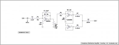
The circuit below is not a build-it project, it's just to show you what kind of thing you're looking at. Just to mention a couple of points, note that:
a. C1 should be omitted if the preceding audio source has a capacitor output.
b. U1 is an isolation stage, U2 is a high-current driver stage (the NJM4556s are in parallel).
c. Inverting configuration is used purely in an attempt to work around the NE5532's annoying bias current. If a similar circuit is built and DC errors are found to be small, then C2 can be omitted.
d. Non-inverting configuration could just as well be used, and would have some advantages, but in that case C2 would be mandatory. Which I personally think is just fine, but some people get excited about that kind of thing.
The NE5532 costs in the 50 cent range on eBay. I semi-recall that the NJM4556 goes for about 80 cents when you get it from Mouser or similar, but that will involve something like a $5 shipping charge (so buy some other stuff at the same time).
.
Attachments
Last edited:
A typical headphone output will never drive multiple phones through a passive distribution system. It might be doable if the distribution system was driven by an audio amplifier capable of at least a couple watts output.
I can understand wanting to avoid the extra complexity of an active distribution system. So if you want to go cheap, maybe you could drive a passive distribution system with a couple of LM386 chips powered by a wall wart. The 386 outputs 1 watt into 8 ohms with a 12 volt supply, according to its datasheet. It is cheap and commonly available. It works with a just a few external parts and is virtually foolproof. It is typically available in a DIP-8 package and requires no heatsink. Coupled with low value potentiometers, it might work for your application.
Bentsnake's solution is much better and still uses easy to get, cheap parts. Be cautioned that an inverting amplifier's frequency response can be affected by a high impedance source (like a tube preamp). It is good practice to use a non-inverting buffer on the input of an inverting amp; this makes its application universal. In fact, some inverting circuits (not this one) are unstable when the input is open or connected to a high impedance source; this makes the buffer virtually mandatory.
A Behringer MICROAMP HA400 is only 25$ (free shipping) on amazon and does all that you ask. And there are dozens of alternatives at the same price. It's difficult to justify going diy on that one...
A Behringer MICROAMP HA400 is only 25$ (free shipping) on amazon and does all that you ask. And there are dozens of alternatives at the same price. It's difficult to justify going diy on that one...
Well this is kind of embarrassing, but 00940 is right, the HA400 exactly fills the bill. And once you figure in power supply and housing it might cost the same or less.
It's embarrassing because I have one right over there on my desk. I guess it's so familiar it's become invisible, but it's been running for, dunno, 2-3 years without a hiccup, highly recommended.
.
- Status
- Not open for further replies.
- Home
- Amplifiers
- Headphone Systems
- Headphone distribution block (passive)